To download this app, visit: Library.
This article describes the tables used in the assembly template and the configurations necessary for the application to function correctly.
- The template offers two options for starting, depending on the type of information provided in the identification label.
- The description also covers important triggers and their logic in the system.
The assembly template app is part of the Traceability App Suite. If you'd like to learn more about the Traceability App Suite, you can explore more information through this link: Traceability App Suite.
Overview
The Assembly App is used to verify components and complete the assembly process for a selected work order.
Hybrid Functionality of the Application
The application operates in a hybrid mode, combining both dynamic and static features:
-
Dynamic Material Identification:
- The app dynamically manages material identification, meaning it can handle changes to component material IDs without issue.
-
Static Assembly Instructions:
- The assembly instructions are fixed within the app, ensuring that while component materials may change, the product assembly process remains the same.
Benefits of the Hybrid Approach
-
Ease of Management:
- With this approach, you no longer need to update the app every time a material changes. You don't need to re-test or approve the app for each material update.
-
Efficient Updates:
- Only the BOM (Bill of Materials) table needs to be updated when changes occur in materials, simplifying the process and reducing the need for frequent app updates.
This hybrid solution ensures a more flexible and user-friendly experience, streamlining processes and minimizing disruptions when materials change.
Tulip Tables in the app
Comments and Exceptions
In the Assembly App, comments created during the process are saved in the Comment and Exception tables.
When a comment is created, the app automatically saves the following details in the Comment table:
- Work Order ID – Identifies the specific work order where the comment was made.
- Parent Material ID – Links the comment to the related material.
- App Name – The name of the application where the comment was recorded.
- Step Name – The specific step in the process where the comment was created.
- Operator’s Description – The text input provided by the operator.
- Image – If the operator attaches an image, it is stored with the comment.
Each new comment is assigned a status of NEW and a type of MANUAL.
This structure ensures that all comments are properly tracked, making it easier to review issues, follow up on operator inputs, and maintain clear documentation throughout the assembly process.
(Operational Artifact) Work Orders
The production requirements of your operation. These are generated from Orders and represent a demand of specific materials to be produced in order to fulfill the order.
In the Assembly App, the application modifies the completed quantity of an ongoing work order during the process.
This means that as work progresses, the system dynamically updates the completed quantity field to reflect real-time production data. This ensures that operators and supervisors always have an accurate view of how much work has been finished within a specific work order.
(Log) Units
We store the component materials and parent materials in the Log Units table. Within the Regulated App group, we track the process using the status of the parent unit. The statuses are as follows:
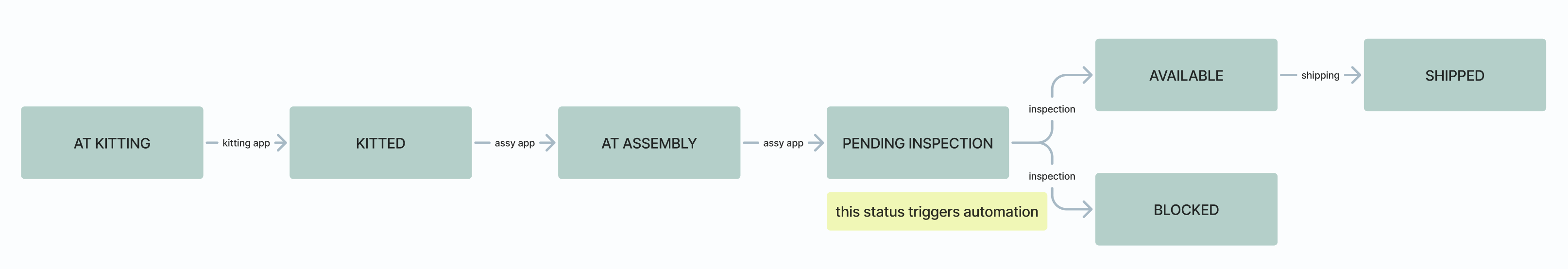
When a parent unit is selected at the start of the Assembly App, its status automatically updates to AT ASSEMBLY. Upon completion of the assembly process, the status changes to PENDING INSPECTION. The PENDING INSPECTION status will trigger the automation process to start.
(Log) Genealogy
Each record is a parent/child relationship. The child could be either a serialized or unserialized subassembly or individual part.
Key Fields:
Parent Unit ID
The unique identifier of the parent assembly, referencing the corresponding unit record from the unit table.
Parent Material Definition ID
Represents the material definition of the parent unit, linking to the Material Definition Table.
Component Unit ID
The unique identifier of the component unit (which could be a serialized or unserialized subassembly or individual part).
Component Material Definition ID
Links to the Material Definition Table for the component unit/part.
Work Order ID
Links the parent-child relationship to a specific work order from the Work Order Table.
Simulation Buttons

In the app, there are several buttons displayed in Rose color. These buttons are only for demo purposes and allow users to simulate the app’s functionality using pre-defined data after downloading it.
Key Notes:
- Not needed in the final production environment – these buttons are for simulation only.
- Before deploying the app in a live environment, these buttons must be removed to ensure a clean and accurate production setup.
Configuration and Customization
To use several functions of the application, a barcode scanner is required. You can find more information about setting up barcode scanners at the following link:
How to Set Up a Barcode Scanner
Additionally, a printer setup is necessary for label printing. Supported printers include Zebra printers, and you can find a setup guide for them here:
How To Integrate a Zebra Printer with Tulip
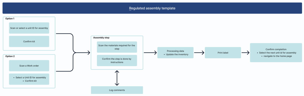
Selection Options in the Application
The application offers two options to choose from. Select the one that best suits your needs—the other option can be removed.
Option 1: Scanning the Unit ID
- The barcode to be scanned contains the Unit ID of the assembled unit.
- The app displays a list of units with KITTED status in a table.
- After selecting a unit, the app navigates to the Confirm Step, where you can see detailed information about the work order.
- Once confirmed, the process moves to the Identify Materials Step.
Option 2: Scanning the Work Order ID
- The label contains the Work Order ID instead of the Unit ID.
- After scanning the work order, the app navigates directly to the Confirm Step, displaying detailed information about the work order.
- The app also lists all KITTED status units related to the work order.
- After selecting the appropriate unit, the process continues with the Confirm Step.
By following these steps, you can configure and customize the application to fit your workflow efficiently
Key Triggers and Logic in the App
Identify Materials Step
- When entering the Identify Materials step, if the componentList and genealogyIdList variables are empty, the lists are populated using aggregations.
- The aggregation process uses Work Order ID and Parent Unit ID to load the lists.
- componentList: This list is filled with the Component Unit IDs (LOT numbers).
- genealogyIdList: This list is populated with the IDs of the records in the table.
Scanning Process
- During the scanning process, the Material Unit ID is scanned.
- If the scanned ID exists in the componentList, the following occurs:
- The Scan Component Unit ID trigger removes the scanned Unit ID from the componentList and transfers it to the scannedComponentList variable.
- The scannedComponentList is used to filter the table of Components Confirmed for Assembly.
Automatic Navigation to Assembly Step
- Once all the Component Unit IDs have been identified and confirmed, the app will automatically navigate to the Assembly Step.
Assembly Step
In the Assembly Step, you can add a guide video or image along with a text description to help users through the assembly process.
- If needed, the process can be broken down into multiple steps.
- Checkboxes can be used to confirm the completion of each step, ensuring the workflow is followed correctly.
- You can mark certain checkboxes as mandatory in the validation rules section of the widget window.
Validation and Interaction Logic
The Completed button can have logic added to it so that it cannot be interacted with until all the required fields (such as the mandatory checkboxes) are filled out.
This ensures that no steps are skipped and the assembly process is completed correctly, as seen in this template example.
Processing Data Step
In this step, the processing data trigger is responsible for updating the QTYs in the Units table after the assembly process.
During the Kitting app phase, the quantity of component units is reduced by the specified amounts and the same quantities are added to the reserved quantity field. This ensures the accurate inventory levels of the materials in stock.
Once the assembly is completed, the app decreases the reserved quantity for the relevant component units, based on the amount needed for product assembly (determined by the genealogy record component quantity).
Automation Results
Additionally, this step includes a table displaying the results of the automation. The automation generates inspection result records for subassembly units that are in the PENDING INSPECTION status, based on the sampling plan.
Optional Adjustments
The table and the Next button can be removed (deleted from the step) if needed, and the processing data trigger can be adjusted so that if the genealogyIdList variable becomes empty, the system automatically proceeds to the next step.