
How To Include Factory Kit Devices in Apps
Learn how to include 5 Factory Kit devices in your apps, including receiving human input and triggering devices based on actions in apps.
The Tulip Factory Kit was the first-touch kit of accessories and hardware for new Tulip users to get started with edge connectivity.
Factory Kit is discontinued as of June 23, 2022.
After you have set up all your Factory Kit devices, you are ready to start building app logic with device inputs and outputs. Usually, this happens within step Triggers and button Triggers.
In this example, we will look at a work instructions app that instructs an operator to assemble a circuit board. The app will work with 5 Factory Kit devices:
- Barcode scanner
- Foot Pedal
- Pick-to-light
- Break beam sensor
- Andon light
In each step of the app, you will learn what is going on in the real world, and how that connects to the Trigger logic in the app.
Here is what the app does:
- Asks an operator to scan the barcode of the part they will be assembling
- Gives a series of work instruction steps. In some steps, the operator must grab a component from a specific bin.
- Ask the operator to inspect the part before they are done
- If the part passes inspection, the app is completed.
- If the part fails inspection, a quality specialist is called over to the station.
Here’s how to use each device in this flow. On the IoT gateway, digital I/O ports 1-8 are found in bank A, while ports 9-16 are found in bank B.
Barcode Scanner
In the first step, an operator needs to scan a barcode before beginning work. The step might look like this:
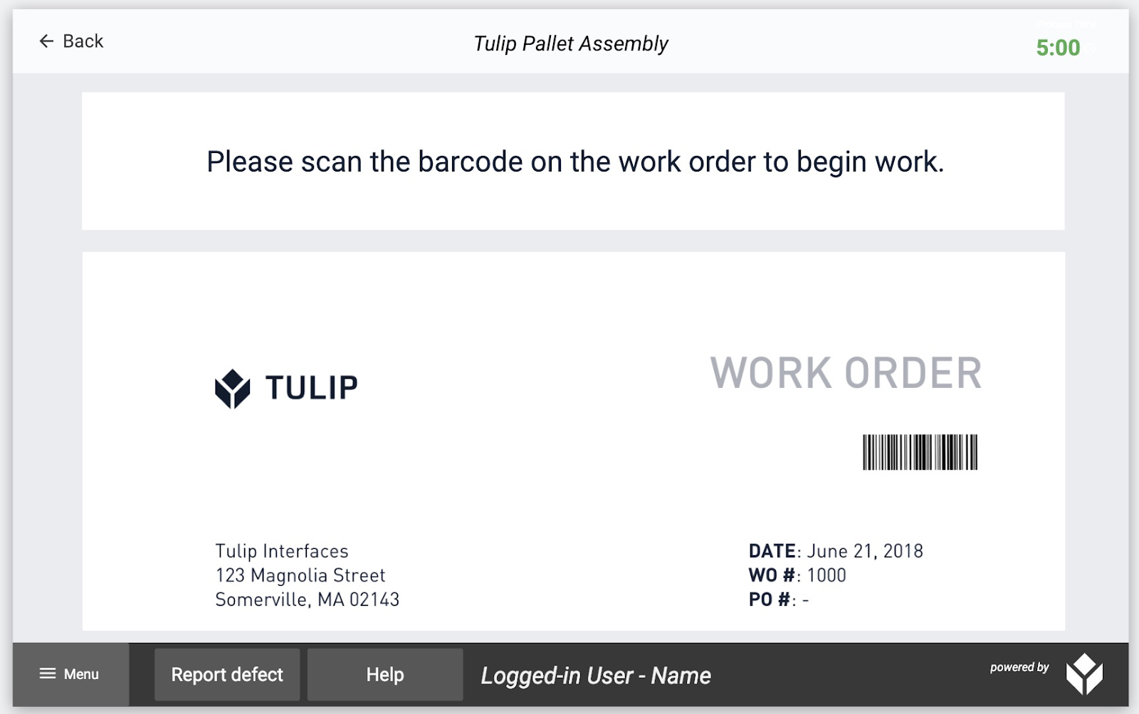
You need to add a step Trigger in order to allow the operator to advance to the next step once they have scanned the work order.
And, you will want to store the barcode number as a variable so that it will be associated with the completion of the app.
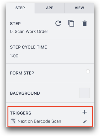
Here’s what the trigger might look like:
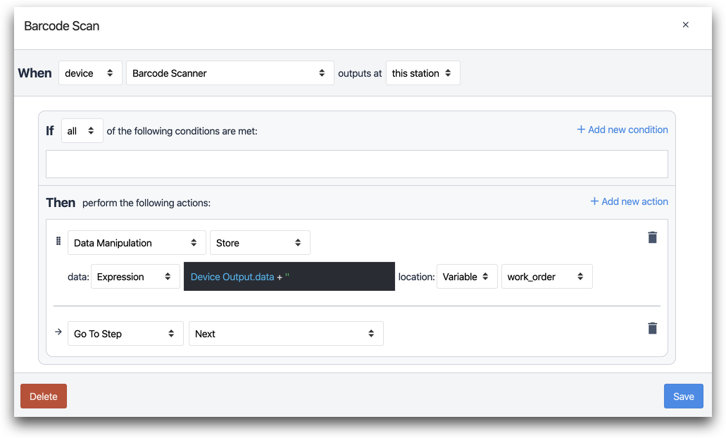
The “When” statement looks for output from the Barcode Scanner:

- "When" "device" "barcode scanner" outputs at "this station"
The first “Then” statement stores the barcode number in a variable called “work_order”:
- "Data Manipulation" "store" data: "Expression" "@Deviceoutput.data +'' "
We recommend that you store barcode values as text values in Tulip, which is why we add a set of quotes and a plus sign in the Expression Editor.
Read more about the Expression Editor
The transition sends the operator to the next step.

- "Go to Step" "Next"
Pick-to-light
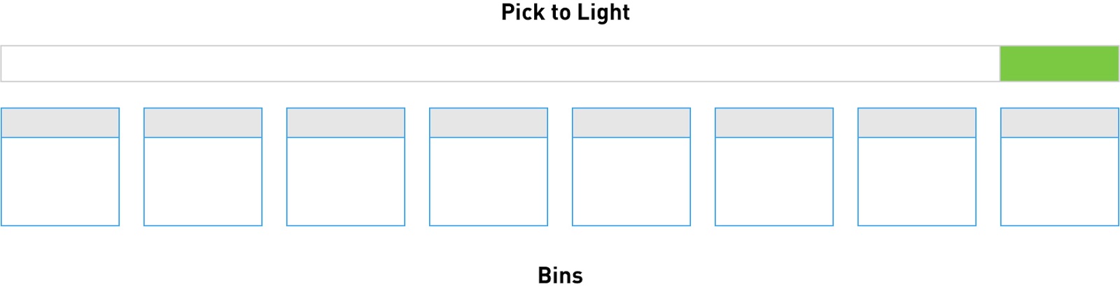
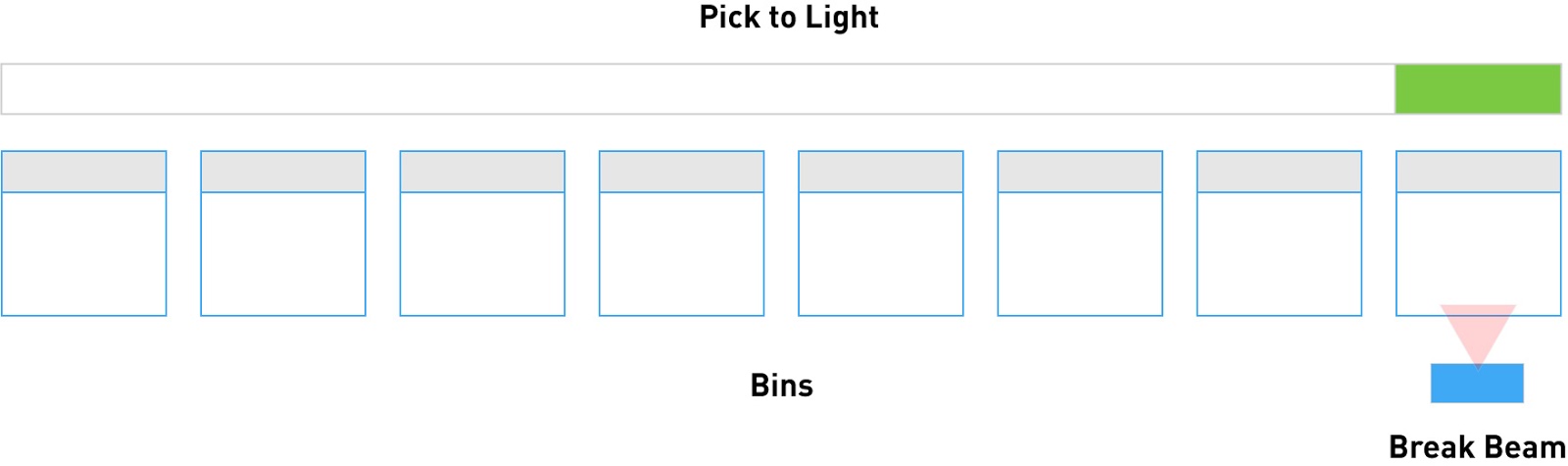
In the next step, an operator needs to grab a white plate from a series of bins at their station. This is the step design:
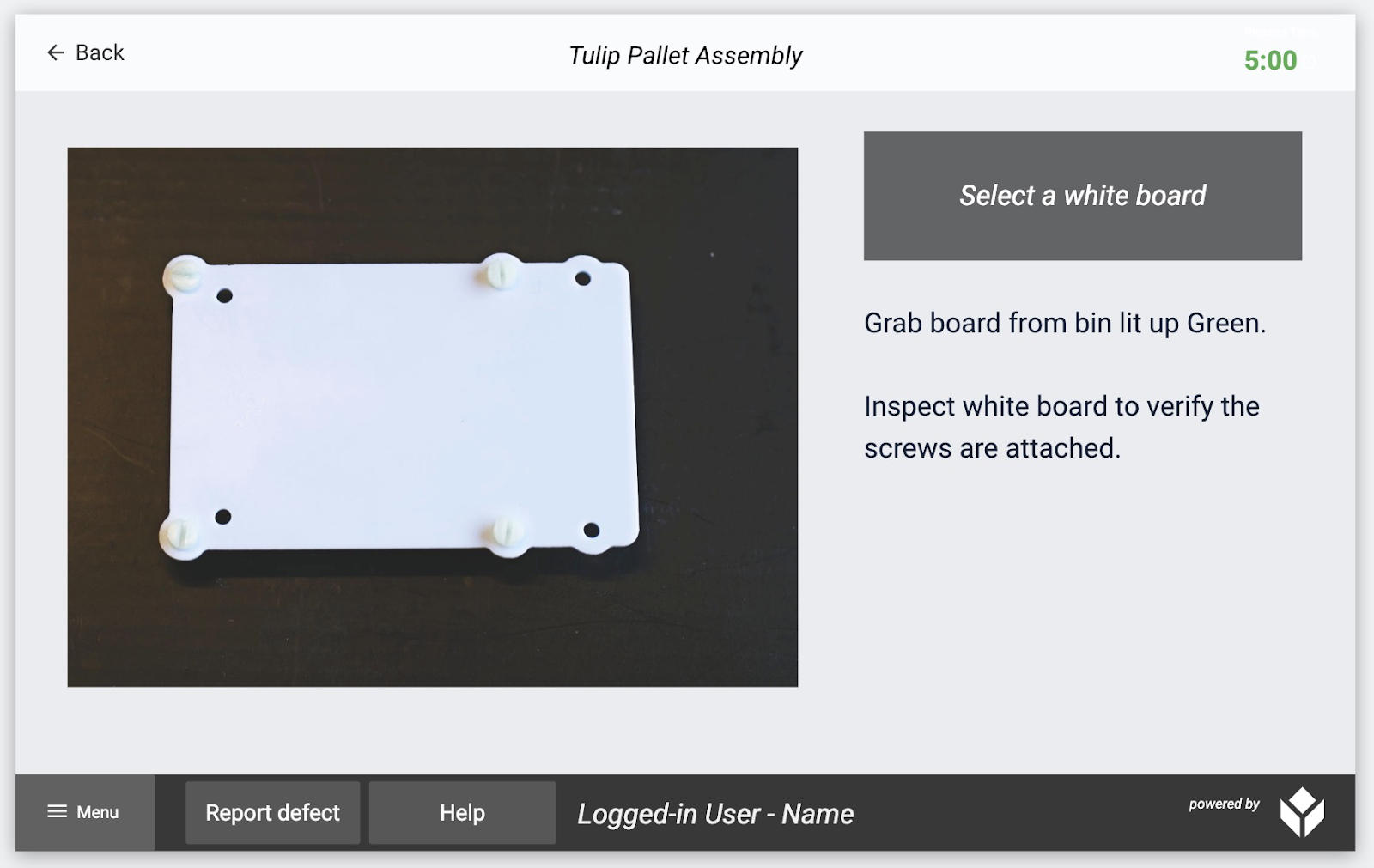
The operator might have a set of 8 bins at their station, and the pick-to-light would light up the 8th one.
You actually need two step Triggers to manage this station:
- When the step opens, light up the appropriate bin
- When the step closes, shut off all lights.
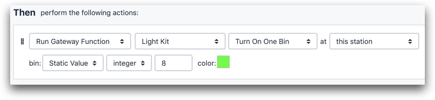
Here is the trigger for the first part:
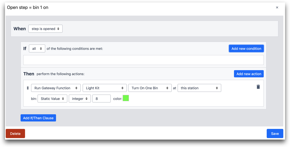
The “Then” statement connects to the Light Kit via the IoT Gateway. Then, it lights up the 8th light on the pick to light strip.

- "Run Device Function" "Light Kit" "Turn on One Bin" at "this station"
- bin: "Static Value" "integer" "8" color: (green)
Here’s the trigger that runs when the step is closed:
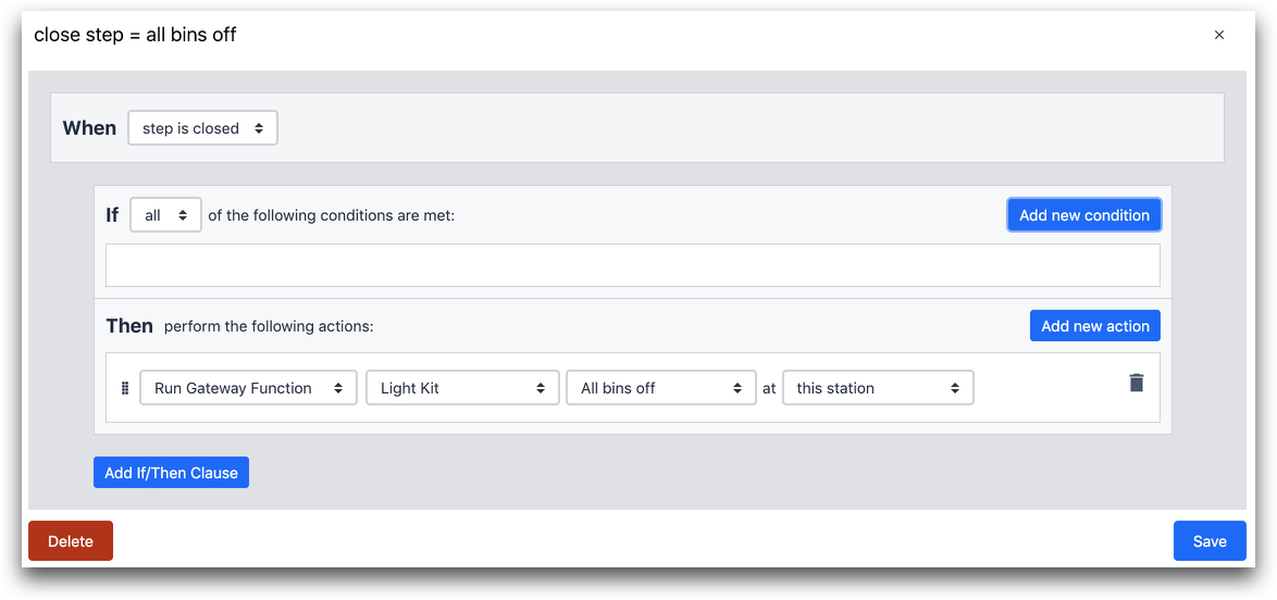
The “Then” statement turns off all lights on the Pick-to-Light.
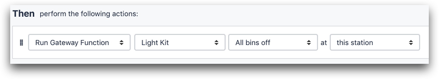
- "Run Device Function" "Light Kit" "All bins off" at "this station"
Break Beam
The Pick to Light cannot accept user input. It can only respond to the events in the Tulip Player.
On the other hand, the break beam can fire a Trigger in Tulip when a person’s hand crosses the sensor.
In order to make this work, you need to create a Trigger on the first step of the app that will power the break beam. That will allow it to start watching for movement across its field of vision.
In order to power the break beam, add this Trigger before the step in the app where you need to watch for movement.
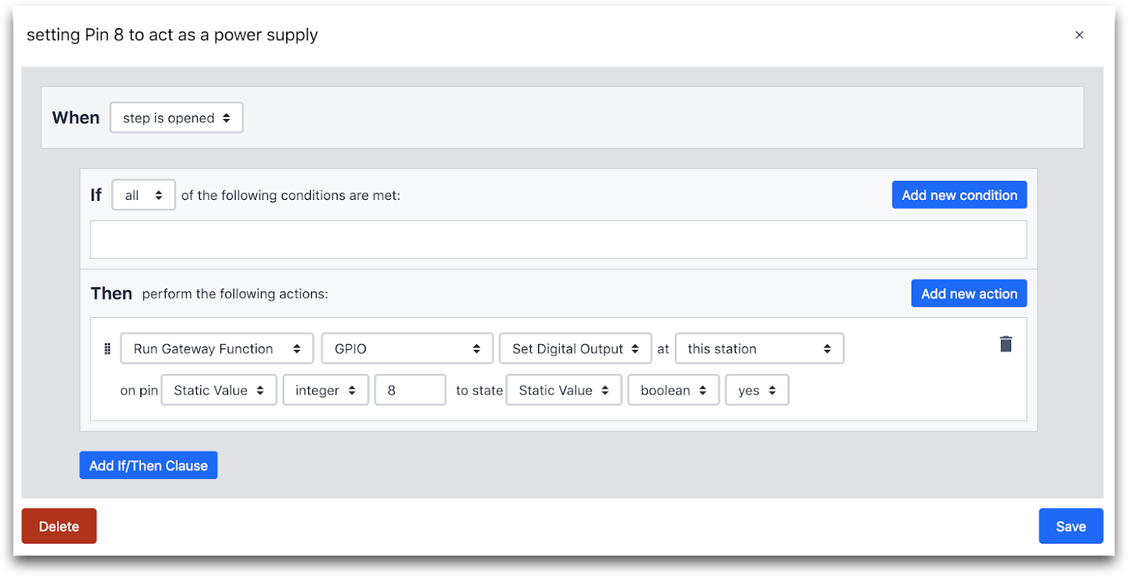
WHEN
- "Step is opened"
THEN
- "Run Device Function" "GPIO" "Set Digital Output" at this station
- on pin: "Static Value" "integer" "8" to state: "Static Value" "boolean" "yes"
Okay, now you are ready to watch for movement on a specific bin.
On the same step as above, let’s say that you only allow want the step to advance after a person successfully picks a part.
Here’s what that would look like:
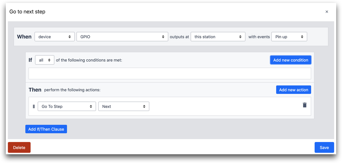
The Trigger fires when the “Pin up event” happens in any of the GPIO ports on the Gateway.

WHEN
- "Device" "GPIO" outputs at "this station" with events "Pin up"
THEN
- "Go To Step" "Next"
If you look at the “A” bank of I/O inputs on the IoT Gateway, you should have a setup like this:
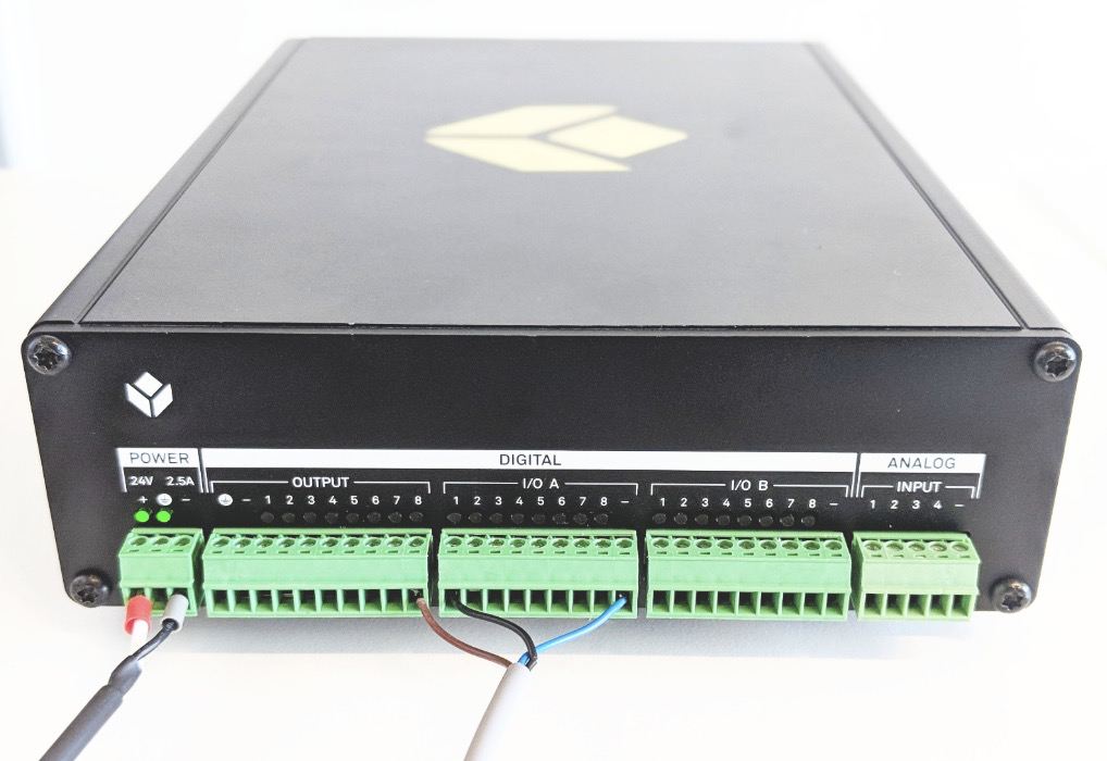
In this case, the break beam is the only device connected to the I/O inputs.
- The brown wire provides power
- The blue wire grounds the device
- The black wire in port 1 of the A bank actually sends the input after something crosses the beam.
So, your Trigger can look for a “pin up” event across all I/O ports. “Pin up” will only fire when something crosses the beam.
Foot Pedal
Let’s say that you want to allow the operator to advance to the next step without touching the screen. The Foot Pedal is a very simple way to accomplish that.
Here’s what the “When” statement would look like:
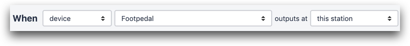
WHEN
- "device" "Footpedal" outputs at "this station"
Light Stack
Let’s say that the operator notices a defect, and you need a way for them to quickly notify a supervisor. The inspection step might look like this:
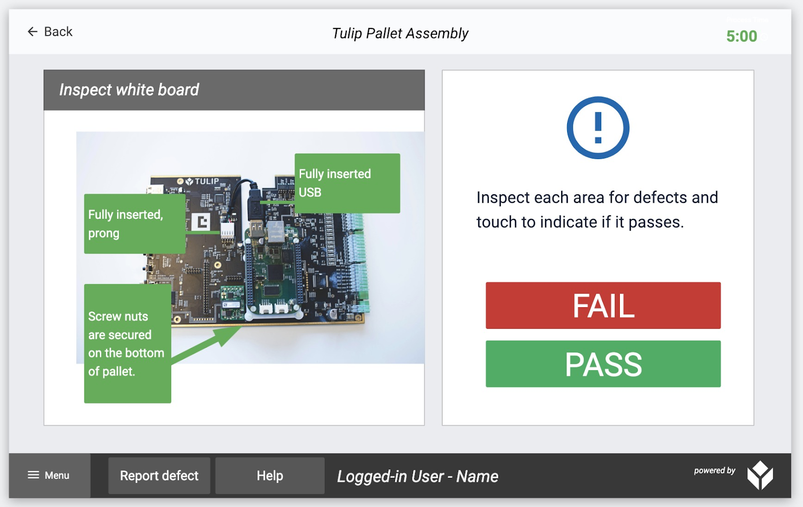
When an operator hits “Fail”, you want the red light on an Andon light to turn on. You can accomplish this with a button Trigger.
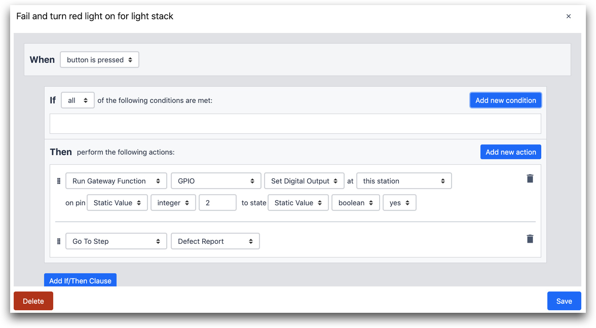
THEN
- "Run Device Function" "GPIO" "Set Digital Output" at "this station" on pin "Static Value" "integer" "2" to state "Static Value" "boolean" "yes"
- "Go To Step" "Defect Report"
In the first “Then” statement, the trigger sends a signal to the 2nd pin in the “Output” section on the IoT Gateway. The red light is connected to that pin, while the green light is connected to the 1st pin (or whatever pin you connected it to).
Then, the operator is sent to a Form Step called “Defect Report”.
Here’s how this Light Stack is connected to the Gateway.
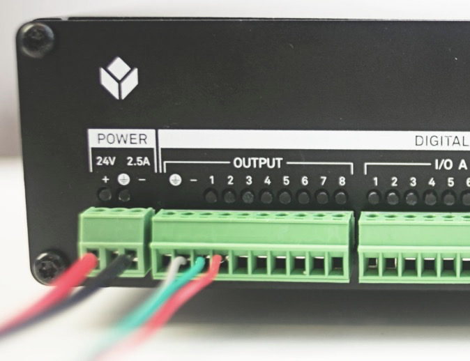
- The white wire grounds the device
- The green light, connected to the green light, is connected to the first pin
- The red light, connected to the red light, is connected to the second pin
So, when the “Then” statement includes “Set Digital Output” that means it can send a signal to one of the 8 “Output” pins.
Further Reading
Here’s a couple ways to learn more about Triggers in Tulip.