
Managing Machine States and Part Counts with Edge IO and Node-RED
Learn how to use the machine visibility Node-RED flow with your Edge IO
This article covers the workflow to connect a break beam sensor and a current sensor to an Edge IO to manage state and count parts in Tulip. This utilizes a Tulip Node-RED library flow that can be imported onto a customer’s edge device.
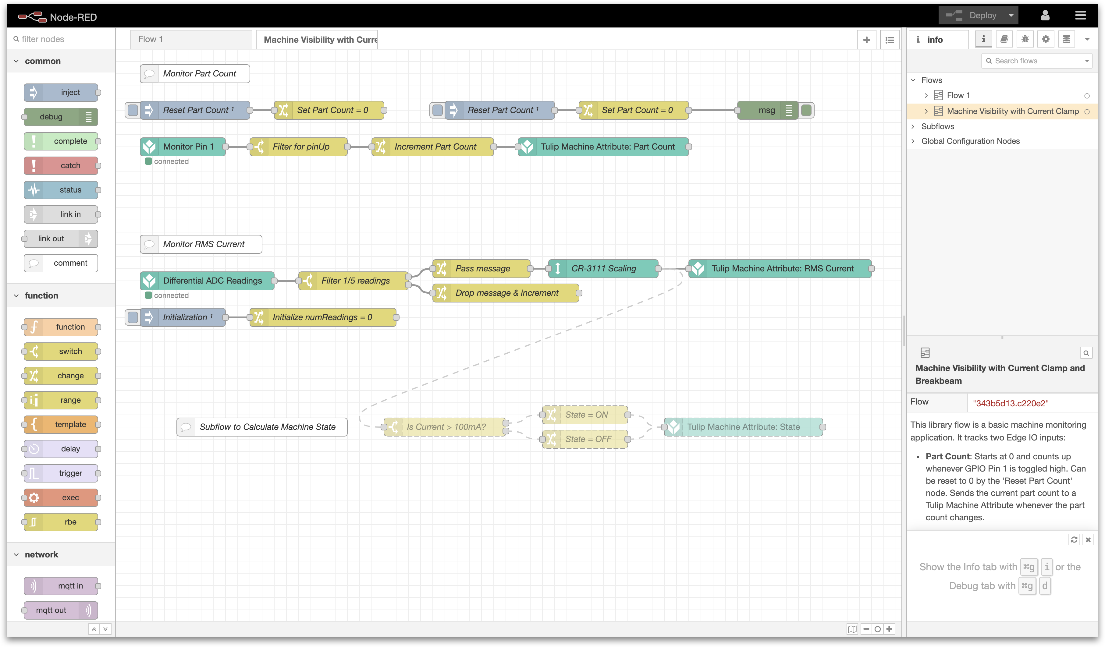
By the end of this article, you will have the following flow within Node-RED to send data from your connected sensors to a Machine within Tulip.
You will need to complete the following steps:
- Hardware Setup: Wire the Edge IO
- Machine Setup: Create a Machine in Tulip
- Node-RED Setup: Import, edit, and deploy a Node-RED flow from the Tulip Library
What you will need is:
-
An Edge IO registered to your Tulip account
-
Current sensor: CR3111-3000 another similar current transformer
- A correctly-sized burden resistor for the current transformer, recommended 100-ohm if the CR3111-3000 (see Hardware Setup for sizing)
-
Break beam
-
3.5mm flat-head screwdriver
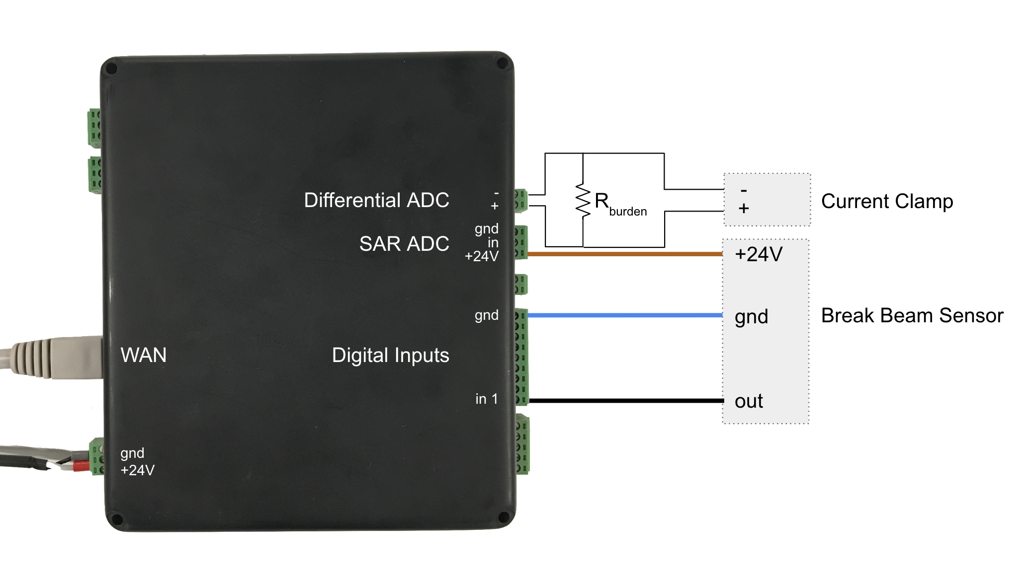
1. Hardware Setup - Wire the Edge IO
This workflow assumes that you’ll be using a current transformer and a break beam connected to an Edge IO.
Calculating the burden resistor size: If using the CR3111-3000, we recommend a 100-ohm resistor. If using a different current clamp, you can calculate the maximum allowed resistor size (R_burden) from the effective turns ration (T_e) and maximum current to measure (I_max) as follows: R_burden = 3.12 * T_e / I_max. Your resistor can be smaller than the maximum allowed resistor size; this will reduce your sensor resolution.
Wire your current clamp (CR3111-3000) and break beam to your Edge IO as follows:
-
Current clamp
- Measuring AC current through the power cable into your machine
- Attach resistor between the two current clamp wires as shown
- Attach one wire to the Differential ADC [+] terminal, and one wire to the Differential ADC [-] terminal
-
Break beam
- Capturing part creation
- Attach brown wire (+24V) to the +24V terminal on the SAR ADC
- Attach blue wire (gnd) to the ground terminal of the Digital Input bank
- Attach black wire (out) to Pin 1 of the Digital Input bank
Additionally, ensure that you’ve powered the device and connected the device to your network by plugging an ethernet cable into the WAN port.
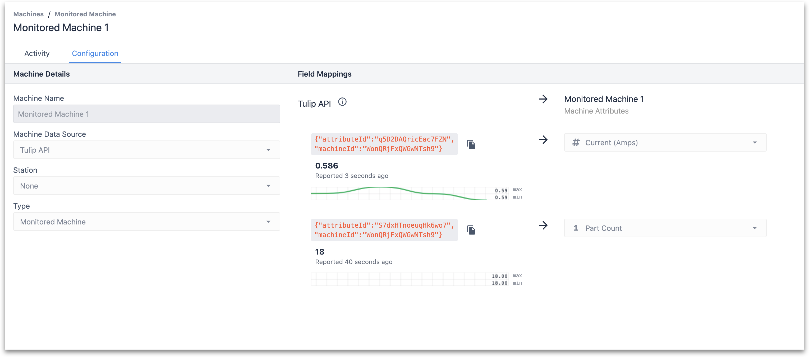
2. Machine Setup - Create a Machine in Tulip
To send data from the break beam and current sensor to Tulip, let’s first set up a Machine using the Tulip API as its data source. Refer to the Setting up a new Machine section of How to Use the Machine Attributes API article for an in-depth overview.
In this example, we’ve created a Machine with two attributes:
- Current (float) - represents the current returned by the sensor.
- Part Count (int) - signal from the break beam indicating the completion of a part.
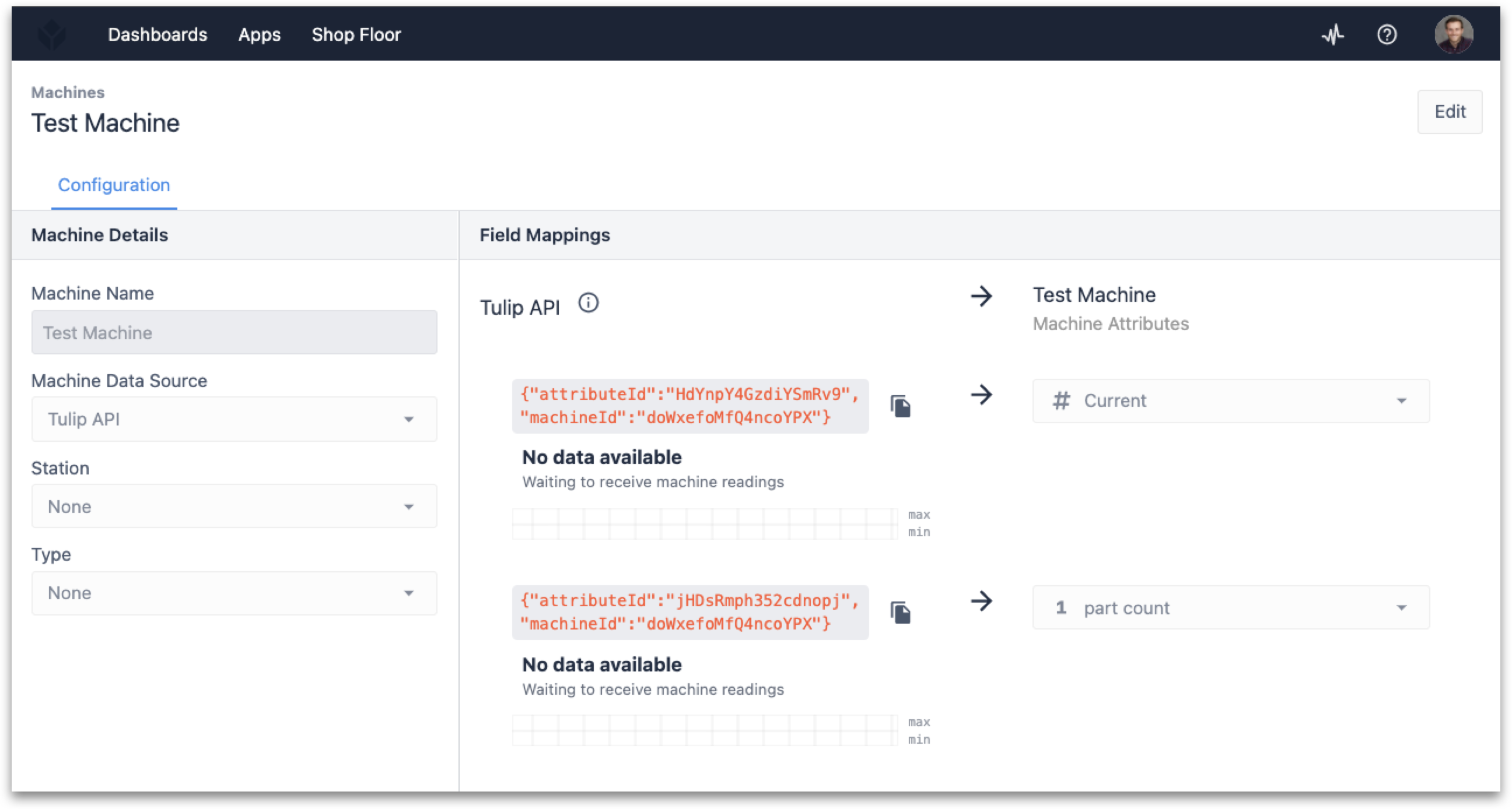
You’ll want to note your attributeIdand machineId values to pass into the Node-RED flow.
You can also set up a Machine Type to assign to the Machine if you plan to use the current sensor to change aspects such as the state of the machine or perform any counts based on the sensor outputs. Refer to How to Set Up Machine Types if this is of interest.
3. Node-RED Setup
Open the Edge Device Portal on the Edge IO connected to the break beam and current sensors. Launch the Node-RED Editor using the following credentials:
- Username: admin
- Password: Your Edge IO password
See more information here to get started with Node-RED on Edge IO.
3a. Import Library Flow
To import the library flow, follow the steps in our Importing Tulip Node-RED Flows document. The flow to import is machine_visibility.json and importing creates the Machine Visibility with Current Clamp and Breakbeam tab in the editor.
3b. Overview of the Flow
This flow is comprised of two separate workstreams:
Part Counter
The first path is to monitor the part count via a break beam sensor. This flow is comprised of four functional nodes:
-
Monitor Pin
- Purpose: Define the GPIO pin(s) on the Edge IO to monitor via the enabled pin property.
-
Filter for pinUp
- Purpose: From the message payload, determine if the event on the monitored pin(s) is true.
-
Increment Part Count
- Purpose: Increment flow variable part count on pin event true.
-
Tulip Machine Attribute: Part Count
- Purpose: Send the payload (partCount) to Tulip via API.
Monitor RMS Current
The second path is to monitor a current sensor connected to the ADC (analog-to-digital converter) input. This flow is comprised of six functional nodes.
-
Differential ADC Readings
- Purpose: Assign the analog configuration profile to the ADC input.
-
Filter 1/5 readings
- Purpose: Extract every fifth measurement (5 seconds) to pass to Tulip.
-
Pass message
- Purpose: Reset the count of readings for every fifth message back to zero.
-
Drop message & increment
- Purpose: For all other readings, increment the count of readings by 1.
-
CR-3111 Scaling
- Purpose: Scale the sensor measurement based on the manufacturer's specifications.
-
Tulip Machine Attribute: RMS Current
- Purpose: Send the payload (partCount) to Tulip via API.
There are also four optional nodes that are disabled by default but can be enabled to have a machine state determined by Node-RED. Note that it is also possible to use Machine Triggers within Tulip to execute this same logic.
-
Is Current > 100mA?
- Purpose: Check if the current value is greater than 100 mA.
-
State = ON
- Purpose: Set payload to ON if the current is greater than 100 mA.
-
State = OFF
- Purpose: Set payload to OFF if the current is less than or equal to 100 mA.
-
Tulip Machine Attribute: State
- Purpose: Send the payload (state) to Tulip via API.
3c. Edit the Flow
To finish setting up this flow, the device info for the Tulip Machine Attribute: Part Count and Tulip Machine Attribute: RMS Current nodes must be included with the attributeIdand machineIdfields from the machine set up earlier.
Depending on the sensor that you use, you can additionally edit the CR-3111 Scaling node to reflect the turns ratio of your current transformer.
3d. Deploy the Flow
With the Node-RED flow built and the necessary parameters added, you can Deploy your flow and begin to see the data from your break beam and current sensors output to Tulip.

By selecting the Debug message option on the right side of the Node-RED Editor, you should be able to see responses and corresponding status codes from the Tulip API.
To get more information about the status codes, please navigate to the API documentation in your Tulip instance (i.e. POST /attributes/report endpoint documentation.
You will now be able to see the data in Tulip as well, by navigating to the configuration tab of the Machine.
Technical Details of the Node-RED Flow
Below is a detailed summary of the nodes and their default configuration parameters imported with the machine_visibility.json file.
Part Counter
-
Monitor Pin
-
Purpose: Define the GPIO pin(s) on the Edge IO to monitor via the enabled pin property.
-
Node type: Digital input
-
Default properties:
- Run Mode -
Continuous - Refresh Rate -
1 second - Enabled Pins -
1
- Run Mode -
-
-
Filter for pinUp
-
Purpose: From the message payload, determine if the event on the monitored pin(s) is true.
-
Node type: Switch
-
Default properties:
- Property -
msg.payload - Rules -
is true
- Property -
-
-
Increment Part Count
-
Purpose: Increment flow variable part count on pin event true.
-
Node type: Change
-
Default properties:
-
Rules:
- Set
flow.partCountto expression$flowContext('partCount') + 1 - Set
msg.payloadtoflow.partCount
- Set
-
-
-
Tulip Machine Attribute: Part Count
-
Purpose: Send the payload (partCount) to Tulip via API.
-
Node type: Machine attribute
-
Default properties:
- Device Info* -
{"attributeId":"", "machineId":""} - Attribute Source -
msg.payload
- Device Info* -
-
Monitor RMS Current
-
Differential ADC Readings
-
Purpose: Assign the analog configuration profile to the ADC input.
-
Node type: High speed analog
-
Default properties:
-
Analog Config -
Differential ADC RMS @ 1kHZ- Select ADC to Configure -
Differential ADC - Enabled Outputs -
RMS - Buffer Size -
1000 - Sampling Frequency (Hz) -
1000
- Select ADC to Configure -
-
Data Type -
RMS -
Output Mode -
Continuous -
Refresh Rate (seconds) -
1
-
-
-
Filter 1/5 readings
-
Purpose: Extract every fifth measurement (5 seconds) to pass to Tulip.
-
Node type: Switch
-
Default properties:
-
Property -
flow.numReadings -
Rules:
== 4otherwise
-
-
-
Pass message
-
Purpose: Reset the count of readings for every fifth message back to zero.
-
Node type: Change
-
Default properties:
-
Rules:
- Set
flow.numReadingsto0
- Set
-
-
-
Drop message & increment
-
Purpose: For all other readings, increment the count of readings by 1.
-
Node type: Change
-
Default properties:
-
Rules:
- Set
flow.numReadingsto expression$flowContext('numReadings') + 1
- Set
-
-
-
CR-3111 Scaling
-
Purpose: Scale the sensor measurement based on the manufacturer's specifications.
-
Node type: Subflow template
-
Default properties:
- Property -
data - Scale* -
3000 - Offset -
0
- Property -
-
-
Tulip Machine Attribute: RMS Current
-
Purpose: Send the payload (partCount) to Tulip via API.
-
Node type: Machine attribute
-
Default properties:
- Device Info* -
{"attributeId":"", "machineId":""} - Attribute Source -
msg.data[0]
- Device Info* -
-
Subflow to Calculate Machine State
-
Is Current > 100mA?
-
Purpose: Check if the current value is greater than 100 mA.
-
Node type: Switch
-
Default properties:
-
Property -
msg.data[0] -
Rules:
> 0.1otherwise
-
-
-
State = ON
-
Purpose: Set payload to ON if current is greater than 100 mA.
-
Node type: Change
-
Default properties:
-
Rules:
- Set
msg.payloadtoON
- Set
-
-
-
State = OFF
-
Purpose: Set payload to OFF if current is less than or equal to 100 mA.
-
Node type: Change
-
Default properties:
-
Rules:
- Set
msg.payloadtoOFF
- Set
-
-
-
Tulip Machine Attribute: State
-
Purpose: Send the payload (state) to Tulip via API.
-
Node type: Machine attribute
-
Default properties:
- Device Info* -
{"attributeId":"", "machineId":""} - Attribute Source -
msg.payload
- Device Info* -
-
* Parameters must be updated for the flow to work appropriately. The scale value of the current sensor should be modified per the manufacturer’s recommendation.
Further Reading
- Node-RED's documentation
- Connecting a 4-20 mA Sensor with Edge IO and Node-RED
- Connecting an Analog Oscilloscope with Edge IO and Node-RED
Did you find what you were looking for?
You can also head to community.tulip.co to post your question or see if others have faced a similar question!