Here's how to use the 4 analog inputs with the Generic ADC driver on the I/O Gateway.
On November 1, 2021, Tulip will no longer sell I/O Gateway devices. Edge IO and Edge MC Devices are still available. Learn More
The Generic-ADC driver on the I/O Gateway is used to read the voltage value on each of the gateway's 4 analog channels.
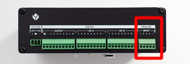
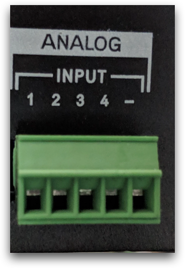
These channels can be located on the "power side" of the gateway at the end labelled "ANALOG INPUT".
Each channel can read between 0-24 volts with an effective resolution of 9 bits, which means it can read voltage changes every 0.002 Volts.
Each channel references its measurement to the the return channel ( - ) on the input. This means that all analog voltage measurements will share the same analog common.
Setting up the Generic-ADV Driver
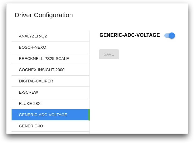
To use these values in Tulip, you will have to make sure that the "GENERIC-ADC-VOLTAGE" driver is turned on in the Device Portal on the Driver Configuration page
Using Analog Inputs in Triggers
To use the data in your app, there are two ways can use triggers to capture this analog data.
- Capturing data when the voltage changes
- Requesting the current value of a channel
Here's an example of how to capture data when voltage changes:
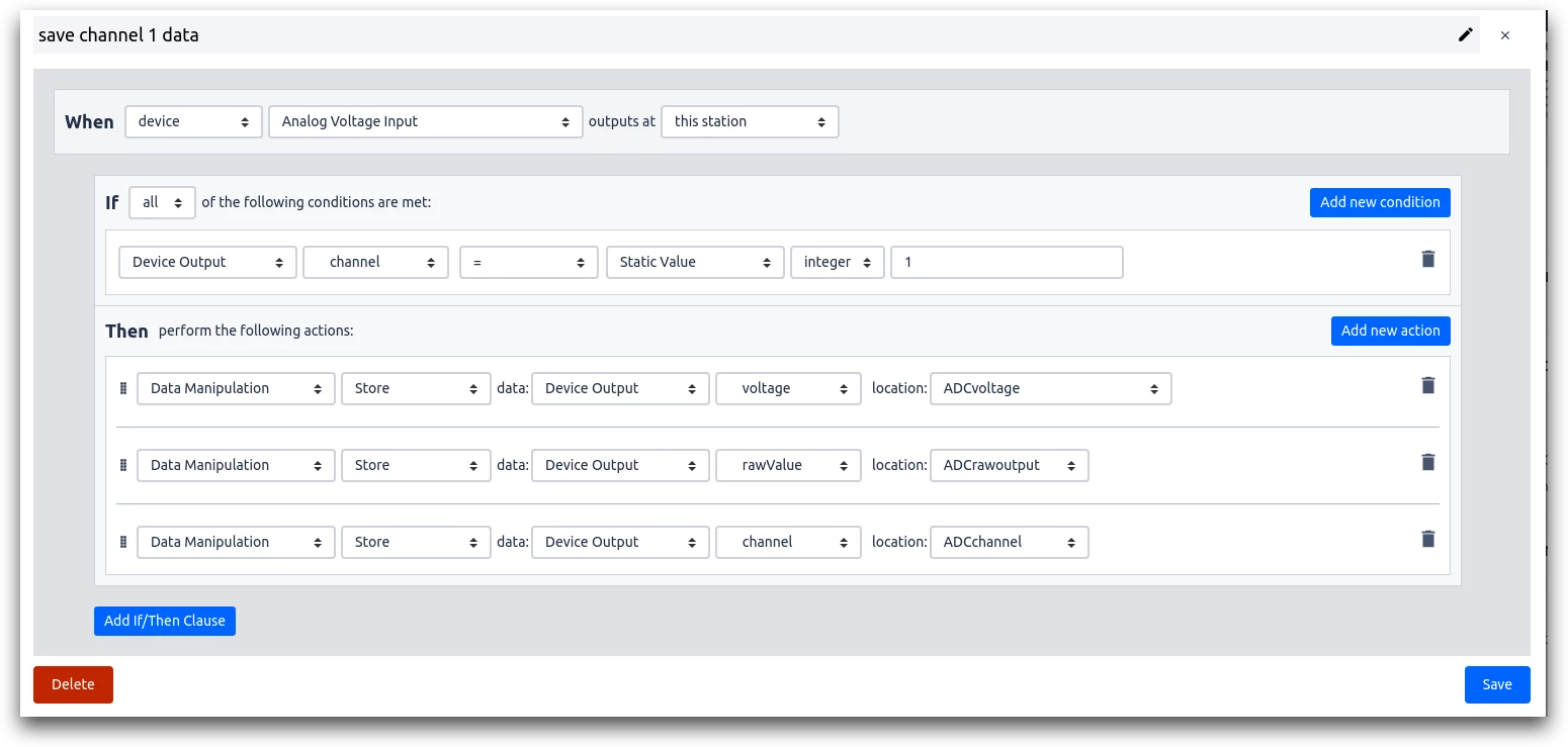
- When "device" "Analog Voltage Input" outputs at "this station"
- If "Device Output" "channel" "=" "Static Value" "Integer" "1"
- Then: "Data Manipulation" "Store" data: "Device Output" "voltage" location: (variable)
- Then: "Data Manipulation" "Store" data: "Device Output" "rawValue" location: (variable)
- Then: "Data Manipulation" "Store" data: "Device Output" "channel" location: (variable)
This method will capture the following data every time the gateway detects that the voltage has changed:
- Voltage
- Raw reading from ADC chip
- Channel
It will not send repeat values. The GENERIC-ADC-VOLTAGE driver will emit data if it detects too much noise on the the single causing the voltage to fluctuate more than 0.002V.
Here's an example of how to request the current value of a channel.
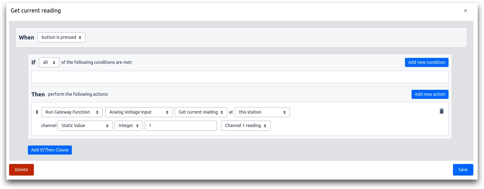
- "When" "button is pressed"
- "Run Device Function" "Analog Voltage Input" "Get current reading" at "this station" channel: "static value" "integer" "1" "Channel 1 reading"
This method will request the current voltage on a specific channel and will return the value even if the reading hasn't changed.
This is necessary for signals from devices such as pressure sensors which, when held at a steady voltage, would not otherwise send an update to Tulip.
Device Examples
This section includes notes for individual devices that can be used with Tulip by using this driver.
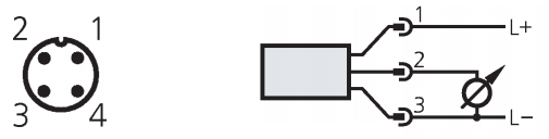
Prosense 25 10-XXXXX
This device provides an output signal of 0-10V depending on the pressure applied to the sensor. A simple proportional relation links the voltage reading from Tulip to the pressure reading. This proportion is dependent on the rated measurement range of the sensor.
The device should be wired according to the instructions in the Datasheet. The wiring diagram is shown below for convenience. In this situation, pin 1 should be provided 24V relative to the ground of the analog input pins, pin 2 should be connected to the analog input pin on the Tulip I/O Gateway, and pin 3 should be connected to the analog input ground.