
Using the Jig Detector
Track objects as they move throughout assembly with Vision's Jig Detector
Before reading this article, please review Getting Started with Vision to get an understanding of Vision's functionalities & requirements, and for instructions on how to setup your camera.
Jig Detector Overview
Using the Jig detector, you can monitor the movement of objects throughout your process. By attaching markers to an object, Vision is able to identify this unique object, and it's movement through pre-defined regions in real-time.
The same jig detector can be used on multiple Stations, allowing you to track an object as it travels from station to station during processing.
In this article you will learn...
- How to setup a Jig Detector
- How to use the Jig Detector in an app
Setting up the Jig Detector
After completing your Camera Configuration setup, you should see the video stream of a Station like this:
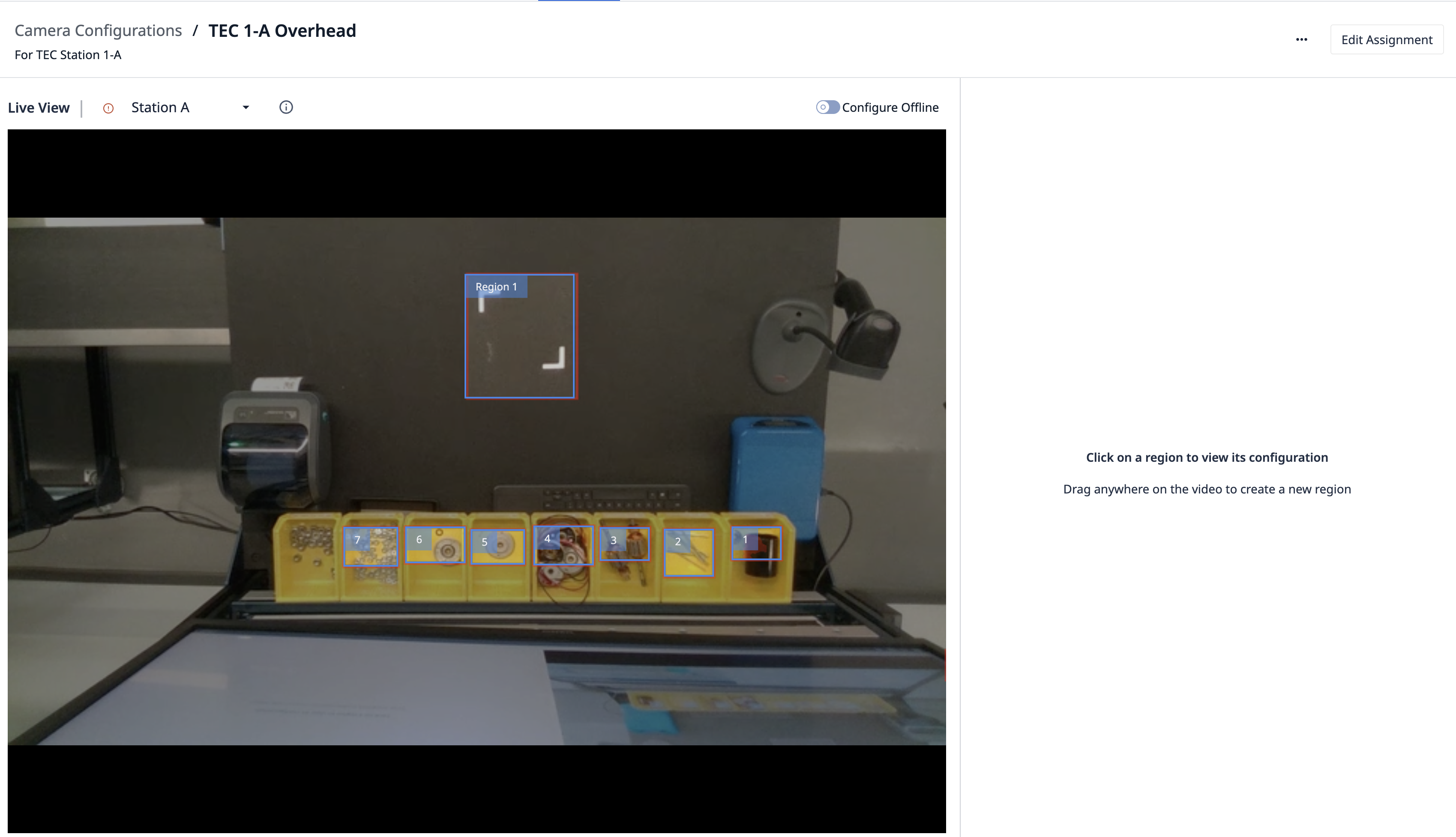
To set-up a jig detector, select the Region that you want to monitor for jigs. To do this, click and drag you mouse to define your region:
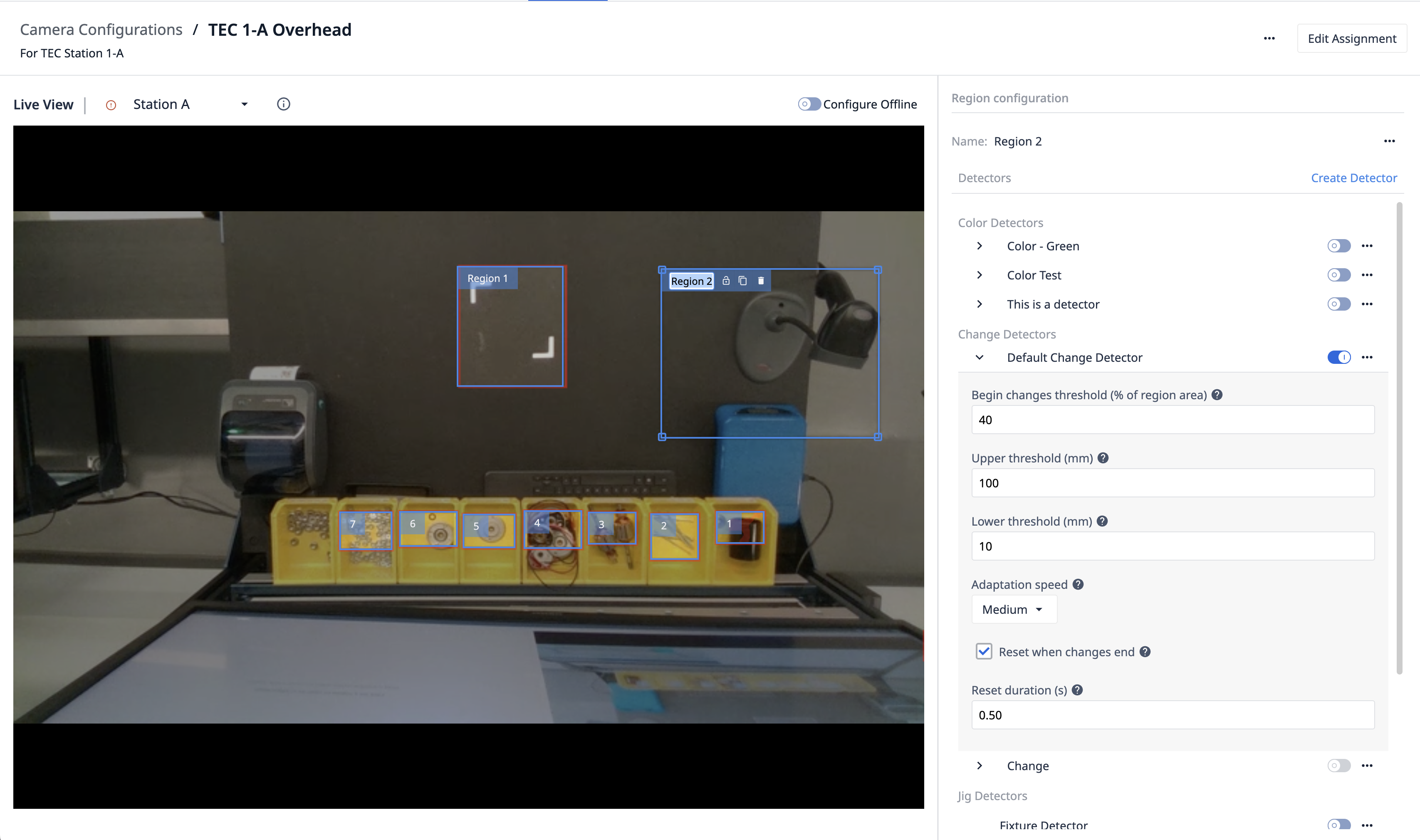
Then name the region, ex: "Material Arrived".
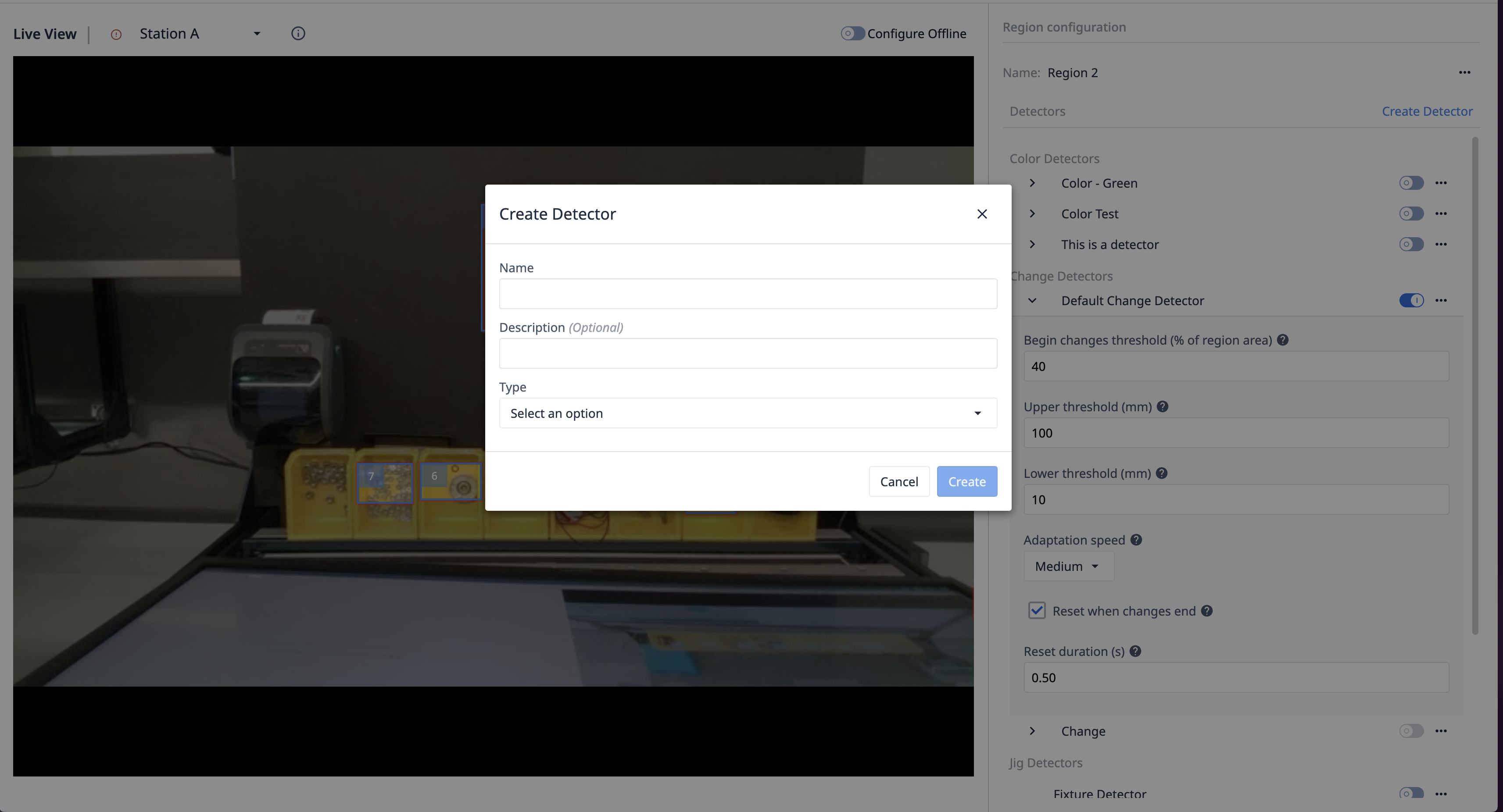
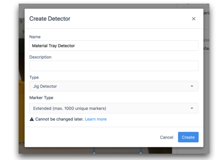
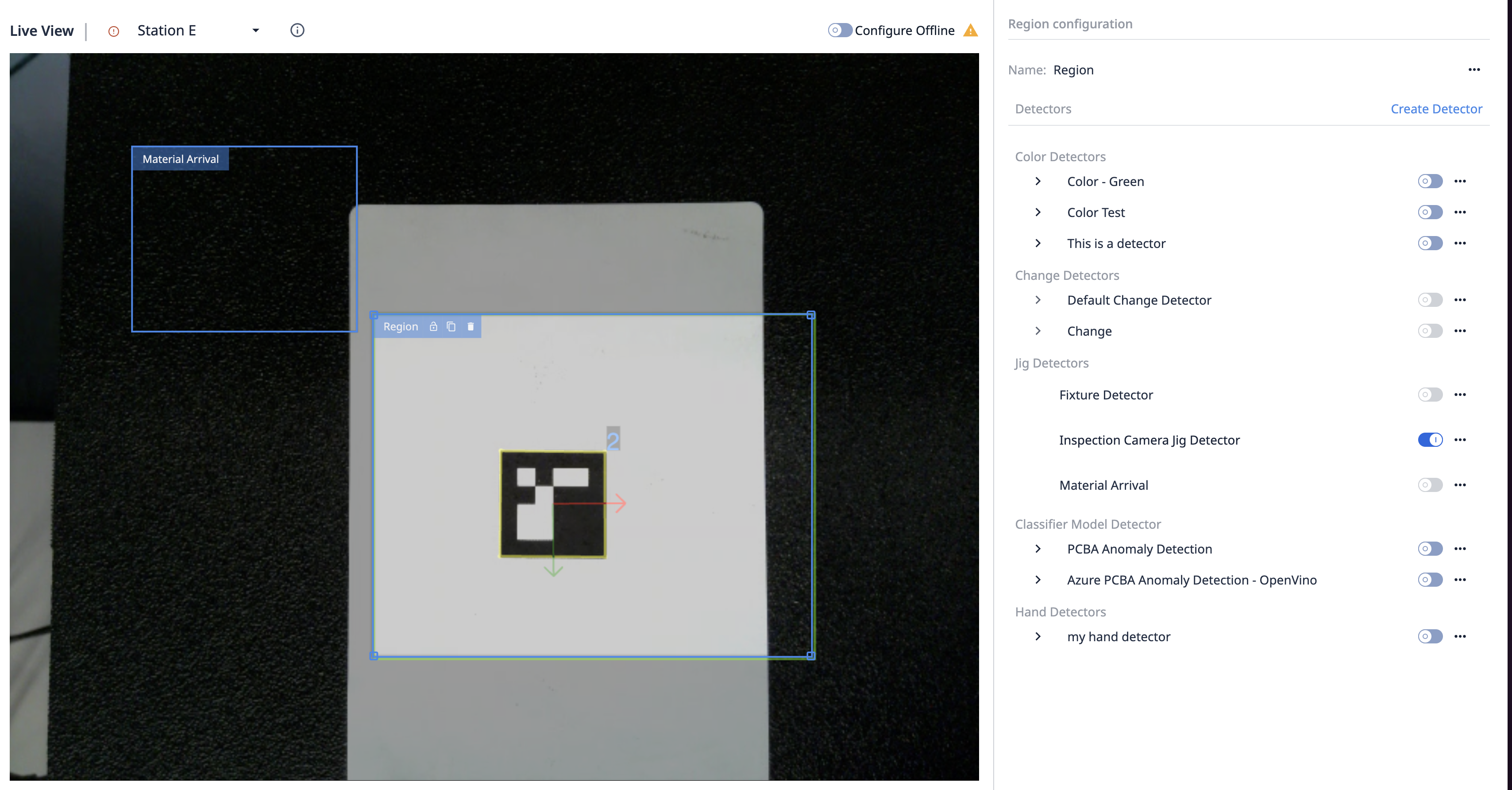
Next, click Create Detector on the right side panel. Enter a name describing the object you want to track. For example, in this walkthrough we are tracking trays with some parts on it.
Please select Jig Detector as the Detector's Type.
Next, you'll be prompted to select your Marker Type. Jigs are tracked by using markers. This Marker Type should be determine by the amount of unique markers you want to have on the object you're tracking. In a later step, these markers will need to be downloaded and printed directly from Tulip, so you can then adhere them to your object.
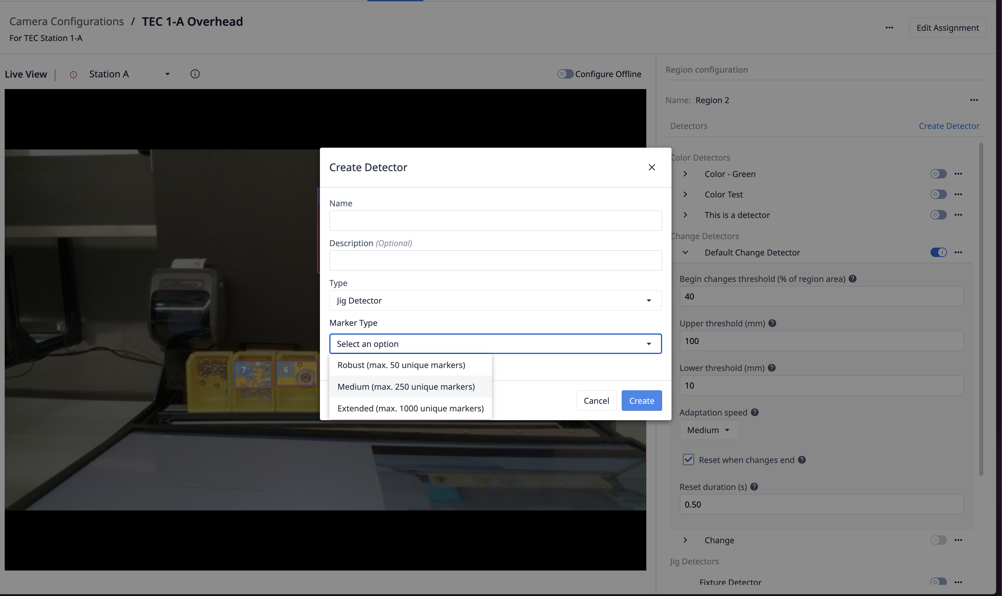
When selecting a Marker Type, keep in mind there is a correlation between how many unique markers that can be detected, and how robust the detection will be. The three "Marker Types" are:
- Robust (max. 50 unique markers)
- Medium (max. 250 unique markers)
- Extended (max. 1000 unique markers)
Assuming you would like to attach 5 markers to each object, and you select a Marker Type of Medium (maximum of 250 markers), then you can track a maximum of 50 unique objects. If you are unsure, select Extended so your detector can track as many markers as possible. Please note that once the Jig Detector has been created, the Marker Type can not be changed.
To finish creating the Jig Detector, click Create.
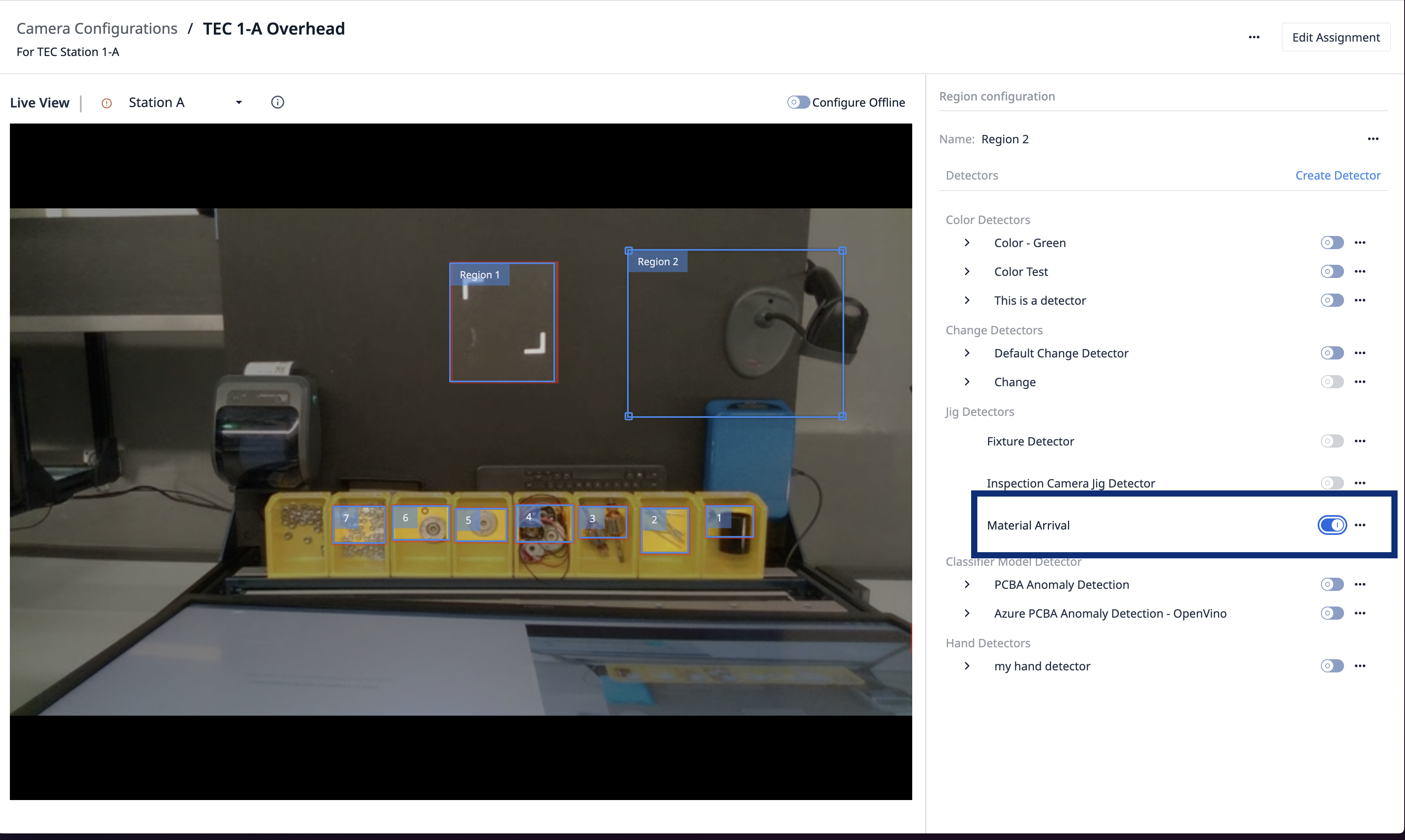
You can now enable the new detector for your region. After enabling it, click on the Jig Detector's name to view its details.
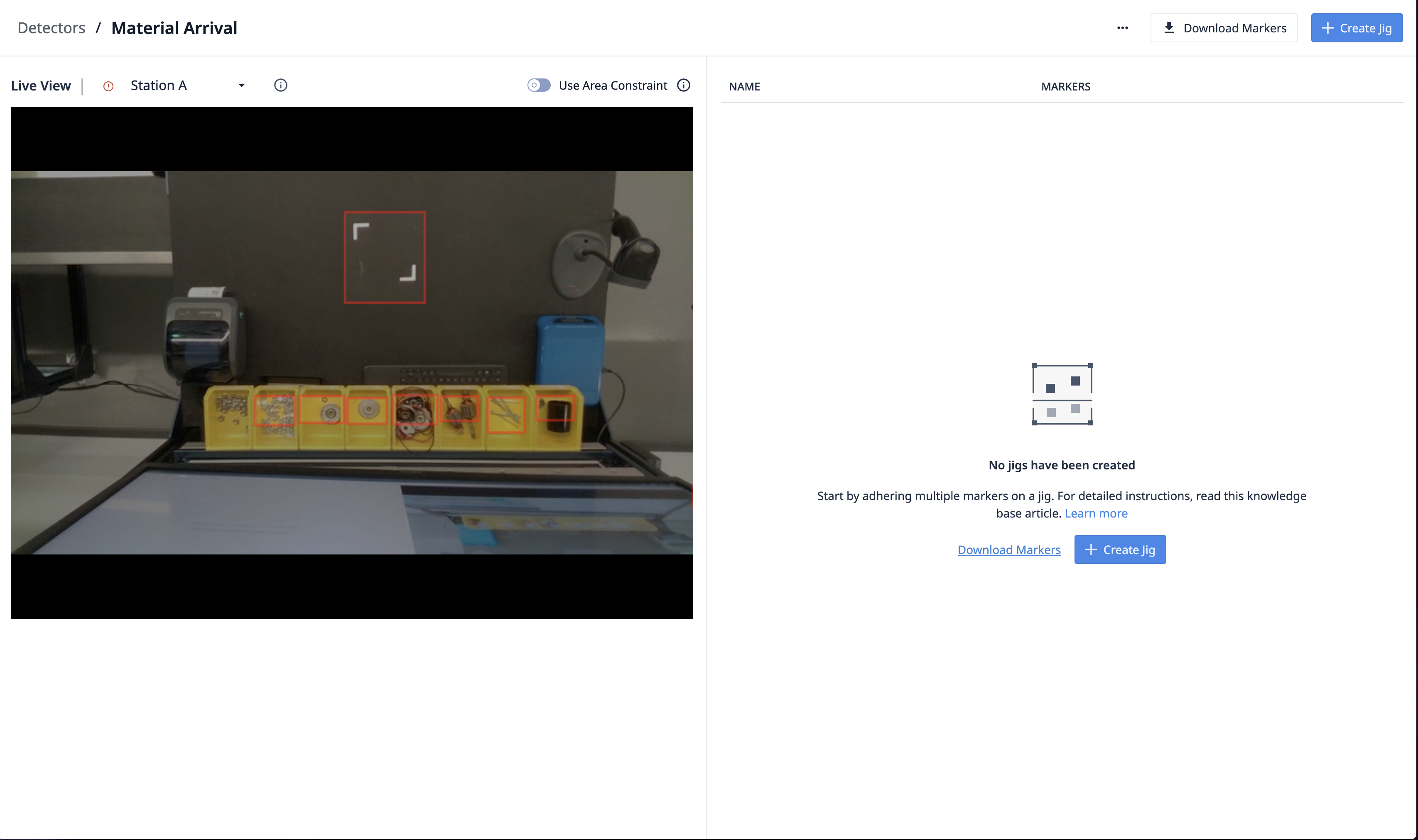
It's now time to setup the physical jigs. You will need to print the markers and adhere them to the object you wish to track.
Click Download Markers to download a PDF file containing all markers. Note, that all markers must be printed at the same physical size. The larger the markers are, the better Vision will be able to detect them. Additionally, the more markers you use for a single object, the more robust the detection will be - if some markers get blocked by an operator's arm or hands for example.
For our demo, we are using a tray with just two markers. You may need to experiment a bit to determine the right size and amount of markers for your use case.
Once you've downloaded, printed, and adhered your markers to your jig you are ready to test the Jig Detector. You should see a blue outline around the markers and the marker ID on top of the video:
Next, please click Create Jig.
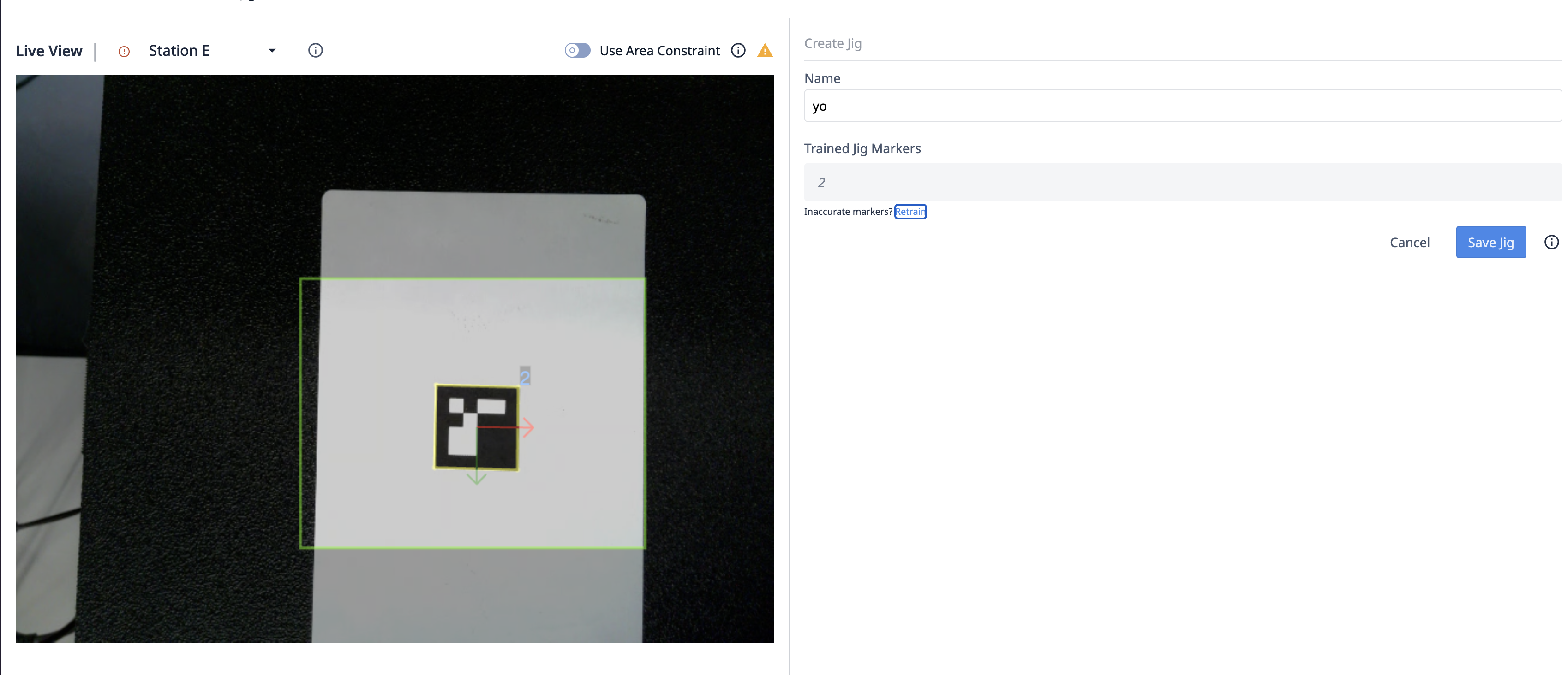
It's now time to train detector. It will learn where you adhered the markers on the object. But first, please make sure to remove all markers that do not belong to your object from the view of the camera. Alternatively, you can use the Use Area Constraint option to limit the area where Vision will monitor for markers.
Next, click Train Jig. The IDs of the marker will appear in the Trained Jig Markers section. For this example, the IDs are "0" and "1". If the IDs don't match the markers you printed and adhered to the object, please click Retrain.
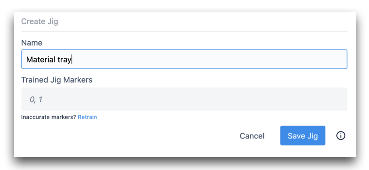
Finally, click Save Jig. A yellow outline will appear around your markers, as well as a coordinate system depicting the origin of the jig:
Jig Detectors, along with the Trained Jigs, can be shared between multiple Camera Configurations. This is important, for example, when jigs travel between Stations. Each station can have different Regions, but still detect the same jigs.
To return to you Camera Configuration page, click your browser's back button. The regions will be shown again:
Using the Jig Detector in an App
Switch over to your app editor, and create a new Device Output Trigger.
All Camera Configurations will appear under the sub-list of Specific device. Please select your Camera Configuration from the dropdown.
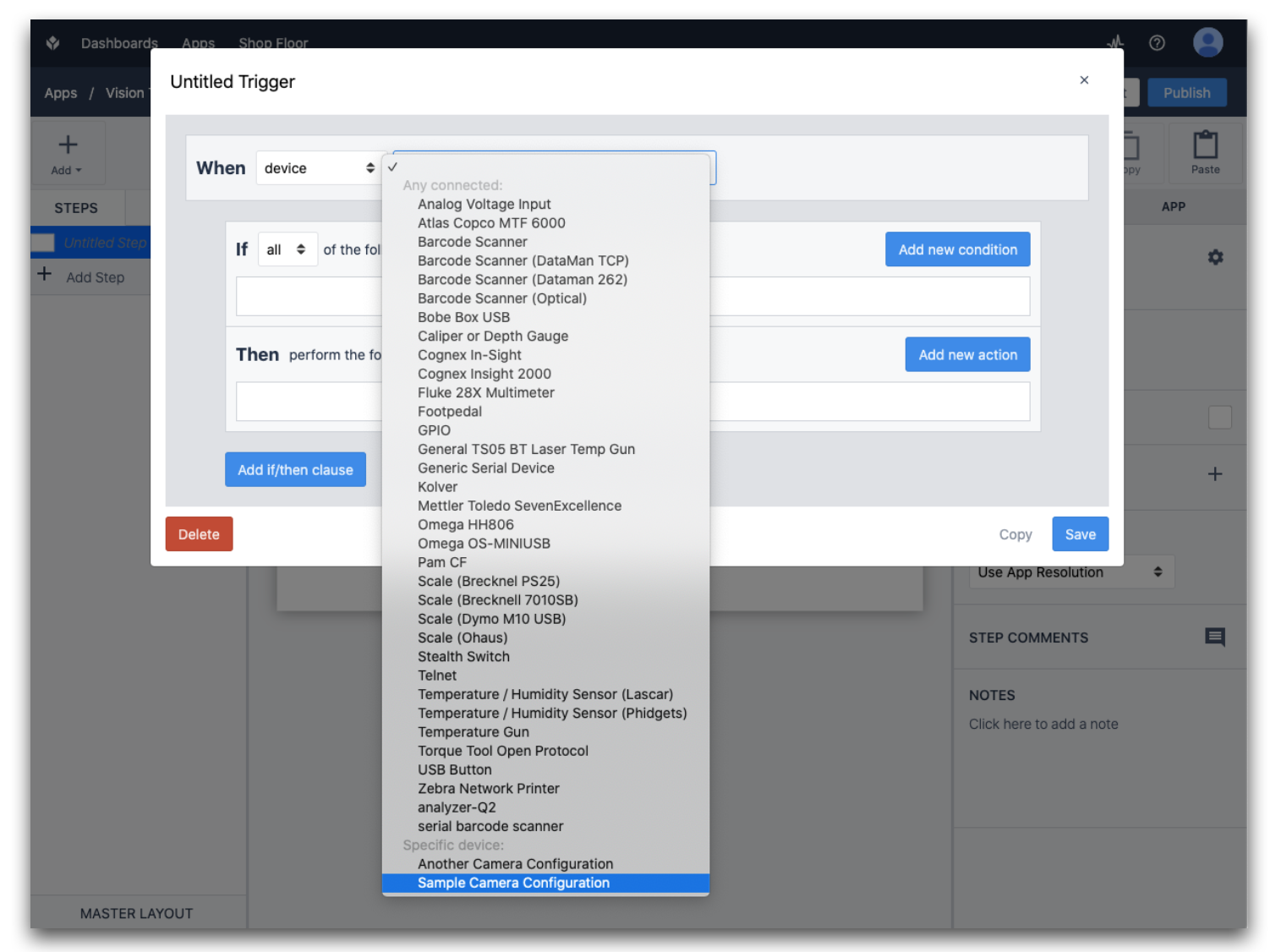
Note, that the Specific device section allows you to use multiple cameras in the same app. Any station that runs this app must have the specific Camera Configuration that you selected for the camera. Otherwise, a warning will be shown when the app runs.
Now you will see a dropdown of various events to run the Trigger off of:
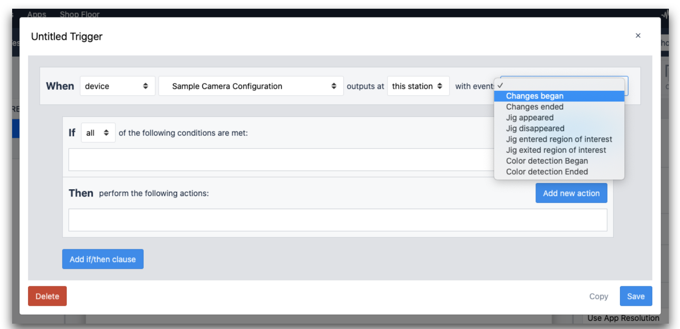
The Jig Detector events include:
- Jig appeared
- Jig Disappeared
- Jig entered region of interest
- Jig exited region of interest
The "region of interest" will be a defined region from your Camera Configuration.
Further Reading
- Using the Change Detector (Requires: Intel D415)
- Using the Color Detector
- Using the Vision Camera Widget in Apps
- Using the Snapshot feature in Apps
- Hardware Recommendations for Vision