
How To Plan Your First Frontline Operations App
This quick guide will simplify the process of mapping your process into a frontline operation app.
Do you currently use PDFs or Excel documents to communicate instructions to your operators?
Or, do you rely on tribal knowledge to share best practices on individual shop floor operations?
If you use either of these common malpractices, then you may need to take some extra time to create a plan for converting your processes to frontline operations apps.
This guide will show you how to create a “process flow diagram”, or a visual map of all the steps that are included in an individual operation AND how to map it to a frontline operations app.
It can be used for visual instructions, control plans, quality inspections or other common procedures. It can also be used to combine documents that were previously separated.
After you create this diagram, you will be able to build a frontline operations app in much less time.
Building an app for a radio assembly process
Here’s an example of a radio assembly process:
In this guide, you will learn how to create a flow diagram for your processes and you will also learn how to map these concepts to individual features in Tulip.
Here is the three-part sequence we will cover:
- Build a process flow diagram
- Turn the diagram into a skeleton of a frontline operation that follows the diagram
- Add content to each step of the app
Major Parts of A Process Flow Diagram
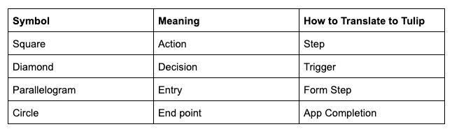
There are four types of steps in process flow diagram:
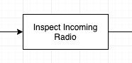
Actions, which are represented with a box
Decisions, which are represented with a diamond
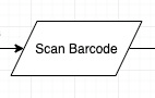
Entries, which are represented with a parallelogram
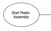
Start/end points, which are represented with a circle
Here’s a specific section of the diagram above that showcases all 4:
Actions are the individual steps that an operator must complete.
Decisions are prompts for the operator to determine whether they should continue to one step or another. For example, if they encounter a defect, you may want to guide them through a rework loop to fix it before continuing with their process.
Entries are stages where the operator must input data, like a work order number, barcode or part weight.
Start/end points will link the operator to another documented process. That process should have its own process flow diagram.
All of these elements are tied together by directional arrows, which indicate the sequence of steps.
Action Item: Before building your first app, draw a process flow diagram for one operation on your floor using pencil and paper or an online tool like Draw.io or Visio. (Expected time: 1 hour max)
To make it easier, you can copy this Draw.io diagram via “File” -> “Make A Copy” to start building your first diagram.
Build A Skeleton of An App In Tulip
Now you are ready to build an app for one operation.
Generally, here is how to map your diagram into an app. There are always exceptions, but this guide should cover all basic and intermediate apps.
Action Item: To build a skeleton of an app, you will need to log in to your Tulip account and duplicate the pre-built “Tulip Terminal” template app This will allow you to easily start adding steps. You can modify the content in the existing steps, if it is easier. (Expected time: 5 min)
If you want a full guide to the capabilities of the Tulip Terminal, read this guide (optional).
For every Action (square) in your diagram, create a normal Step
For every Entry (parallelogram), add a Form Step.
For every Start/End Point (circle), add a step with a Complete button The operator may also need to get redirected to a new app to start another process. If you are using the Tulip Terminal, a Complete button already exists on every step.
For every directional arrow, add a Button on the active Step to advance the operator to a different step. If you are using the Tulip Terminal, a next/back button already exists on every step.
For every Decision (diamond) in your diagram, we will create a Trigger in the next section.
After you have a step or button that corresponds to every step in your diagram, you are ready to start adding content and tracking data with the app.
Here’s what it might look like:
Converting a Process Flow Diagram Into A Frontline Operations App
Create the steps
These 3 types of steps will give you a high-level overview, but they will not give any guidance on how to build the app itself.
For each step, you need to answer three fundamental questions:
- What does the operator need to do? Describe the process in a short sentence with text
- How will they know whether they are doing the right thing? Can you show an image or video? Remember a picture is worth a thousand words.
- Which data need to be tracked? And will the data be collected by a human or IoT device?
Starting with step 1 in your app, go through each step and answer those three questions above. If you are comfortable with the App Editor, you can start building each step.
Action Item: To get comfortable with the App Editor, complete the Tulip Basics tutorial that is loaded into your account (20 min).
Here’s how Tulip customers typically answer each of these questions within each step:
- Add text with instructions via the Widget Bar
- Use media to show good/bad examples with embedded images, videos, GIFs and more using the Widget Bar
- Use **variables to track individual data points. Please note: You will need to create and store these variables within a Trigger. This can be accomplished with a Button Trigger.
Here’s an example of one complete step:
Action Item: Add this content to each step, if you are comfortable with the App Editor (Expected time: 1+ hour).
Add the app logic
Last, you need to set up the triggers for Decisions. These Triggers will allow you to create dynamic logic throughout your app that depend on the button pressed by an operator. You will likely want to track the result of the Decision, so you will need to be familiar with storing values in variables
Here’s one Trigger that fires when an operator does not hear any sound from their radio, and sends the operator to a series of audit steps:
A value is stored in the variable defect_id to indicate that the operator encountered a defect.
Here’s an example of step screenshots that align with the first 4 steps of the diagram above:
Action Item: Review every Decision in your process flow diagram, and ensure you have created a Trigger that will route operators to the correct steps for each one (Expected time: 1+ hour)
Notes and Next Steps
If you plan on using IoT devices for control, you will first need to purchase an Edge Device. Then, check out this guide to Tulip + Edge Devices to learn how to use your specific device with Tulip.
Further Resources
Did you find what you were looking for?
You can also head to community.tulip.co to post your question or see if others have faced a similar question!