Dowiedz się, jak skonfigurować urządzenia Modbus w Node-RED
Ten artykuł obejmuje przepływ pracy do edycji różnych typów węzłów Modbus.
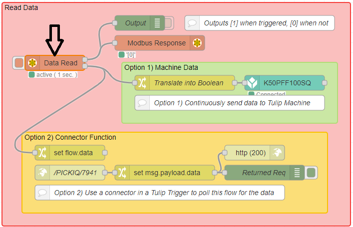
Procedury edytują przykładowy przepływ PICK-IQ Node-RED.
Ensure your Edge Device is fully updated in order to prevent softlocking. If you run into issues connecting Modbus devices, restart Node-RED on your Edge Device.
Edytuj serwer Modbus
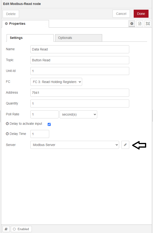
- Kliknij dwukrotnie węzeł Data Read Modbus
- Wybierz przycisk Edit Modbus Server
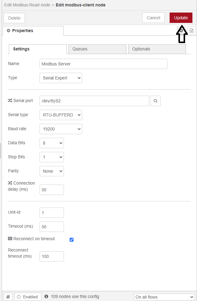
- Ustawienia serwera Modbus
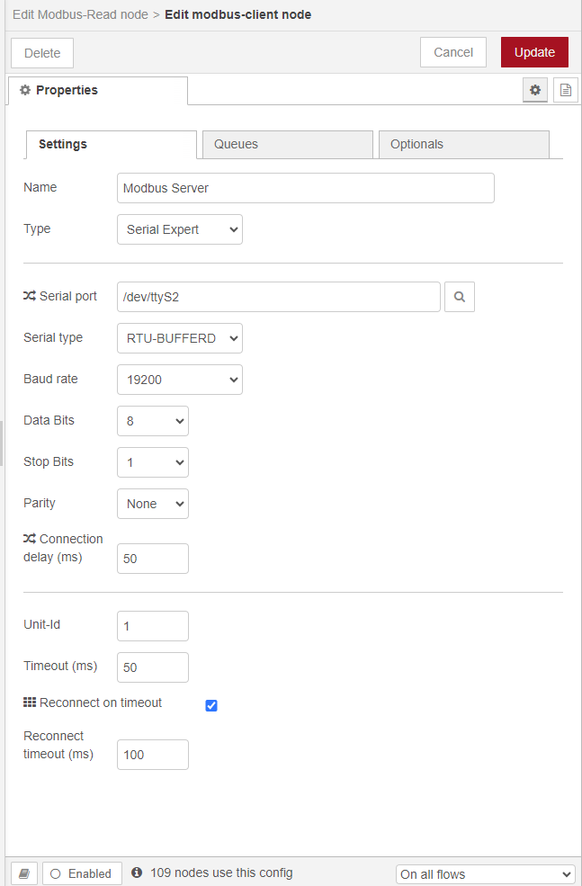
Poniżej znajduje się przegląd niezbędnych ustawień:* Port szeregowy: /dev/ttyS2 (Jest to lokalizacja portu RS-485 w EdgeIO)* Typ szeregowy: RTU-BUFFERD
Następujące ustawienia COM muszą być zgodne z urządzeniem Banner. Aby dowiedzieć się, jak je zmienić w urządzeniu Banner, patrz arkusz informacji technicznych Banner. Poniżej znajdują się wartości domyślne dla urządzeń Banner:* Szybkość transmisji: 19200* Bity danych: 8* Bity stopu: 1* Parzystość: Brak
- Wybierz przycisk Aktualizuj
Zmień identyfikator jednostki
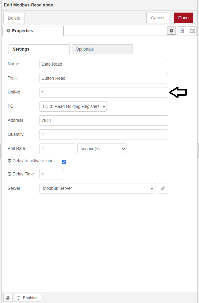
Każde urządzenie ma identyfikator Unit-ID (domyślnie: 1), umożliwiający zaadresowanie konkretnego urządzenia. Jeśli podłączonych jest wiele urządzeń z tym samym identyfikatorem Unit-ID, wówczas wszystkie urządzenia będą kontrolowane przez węzły Modbus odwołujące się do określonego identyfikatora Unit-ID. Jeśli chcesz indywidualnie sterować podłączonymi urządzeniami, musisz:1. Podłączyć pierwsze urządzenie.2. Zmienić identyfikator Unit-ID z domyślnego: 1 na nową wartość (np. 2).3. Kliknąć dwukrotnie dowolny węzeł Modbus, który ma odnosić się do pierwszego urządzenia, aby edytować węzeł.4. Zmienić pole Unit-ID na nową wartość (np. 2).5. Powtórzyć dla wszystkich innych węzłów Modbus, które mają odnosić się do pierwszego urządzenia.6. Powtórzyć dla każdego nowego urządzenia.
Węzeł Modbus może adresować tylko jeden Unit-ID na raz, dlatego może być konieczne użycie wielu węzłów Modbus do indywidualnego sterowania wieloma urządzeniami.
Zmiana adresu rejestru
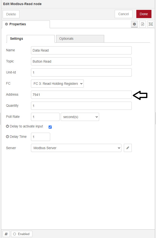
Adres rejestru można zmienić w podświetlonym polu tekstowym. Typowe adresy rejestrów można znaleźć w tym artykule.
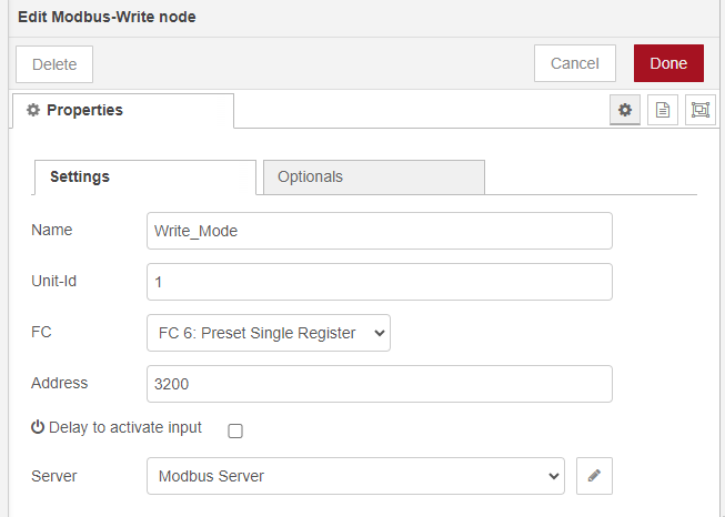
Węzły zapisu Modbus
Te same kroki są wykonywane podczas edycji węzła zapisu Modbus. Jedyną różnicą jest zmiana FC na FC 6: Preset Single Register, zamiast FC 3: Read Holding Register.