
Setting up the Break Beam Sensor
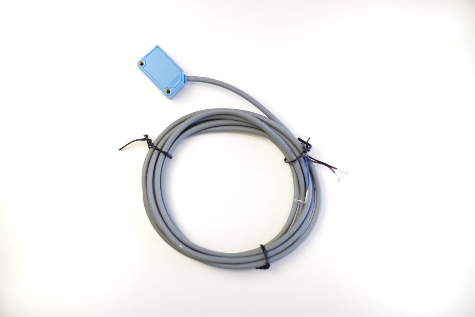
Here's how to connect a break beam sensor to the Edge IO.
The break beam sensor is connected to the Edge IO using the I/O pins located opposite the USB ports.
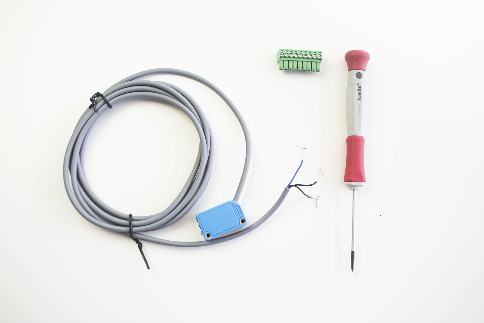
To set up the break beam, you will need to have a 3.5mm flat-head screwdriver.

The break beam sensor needs two things to work with Tulip:
- A 12v power supply
- Connectivity to the Edge IO.
There are several ways to provide power to the break beam sensor. The simplest way, and the way that will be demonstrated in this article, is to supply the power directly from a pin on the Edge IO.
To power the break beam directly from the Edge IO, you will need to:
- Connect the power wire of the break beam to an output connector on the Edge IO.
- Set that pin to be 'on' via Triggers
To wire the break beam (power from Edge IO)
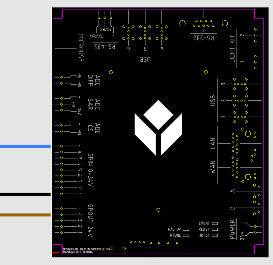
Below is the wiring schematic to connect to your break beam sensor.
How To:
Begin break beam setup by unplugging the Edge IO power. This will ensure you are safe during setup.
Remove a 9-pin and 5-pin connector from the included Edge IO connectors.
In the next steps, you will connect the wires from the break beam to the phoenix adapter and terminal blocks.
Prep the GPIN connector
Use the screwdriver to loosen the screws on the output connector. The output connector has 9 slots.
Wire the GPIN connector
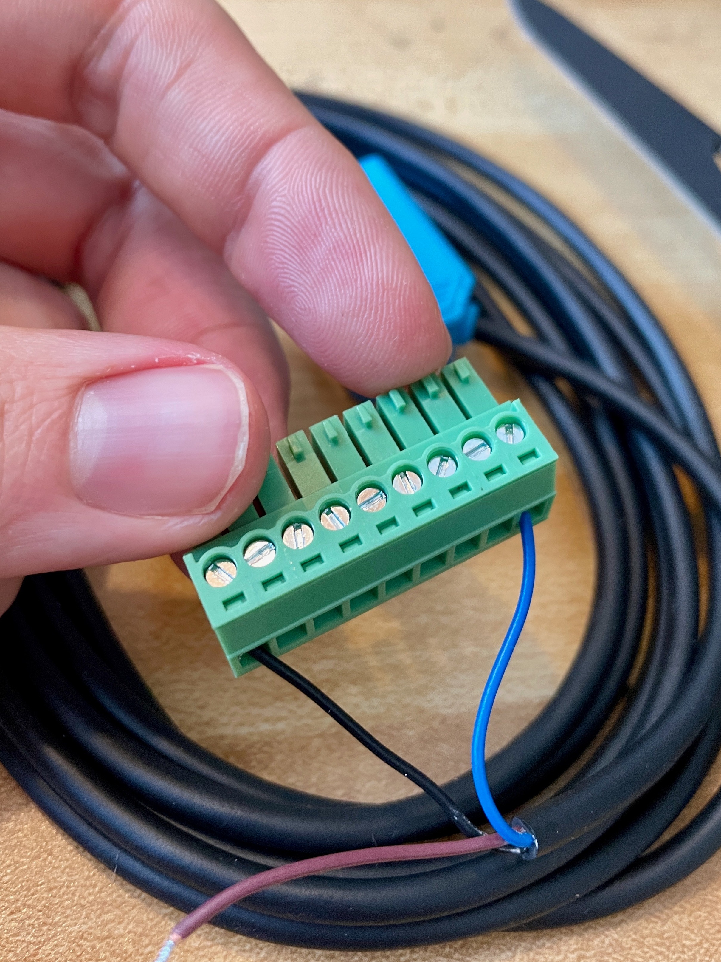
The BLUE break beam wire goes to right most terminal, the BLACK break beam wire goes to the left most terminal. Insert the wire and tighten the screw.
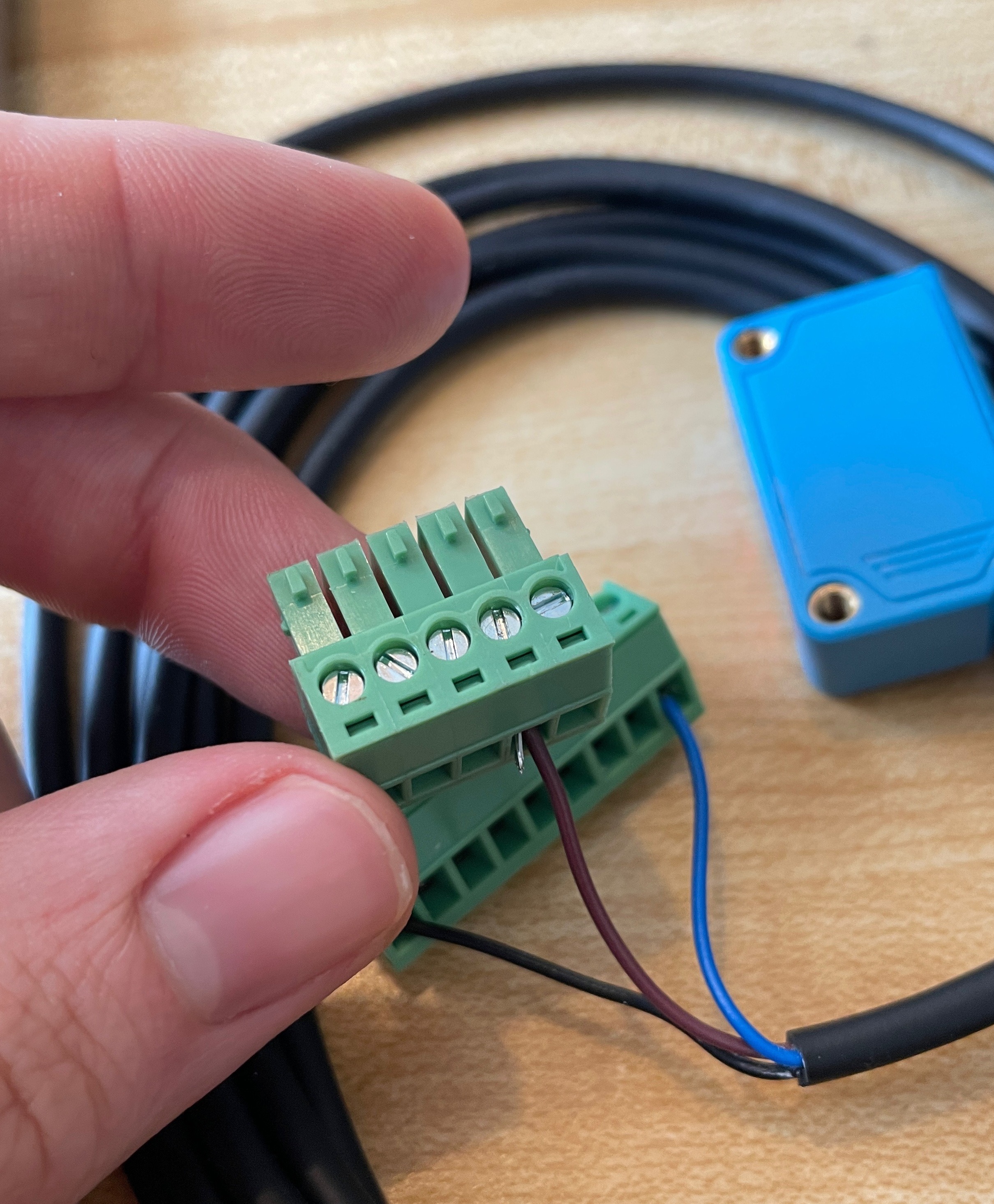
Prep the GPOUT connector
Use the screw driver to loosen the screws on the I/O connector. The output connector has 5 slots. Loosen the 2nd slot from the right.
Install the BROWN wire. Tighten the terminal screw to lock in the brown wire.
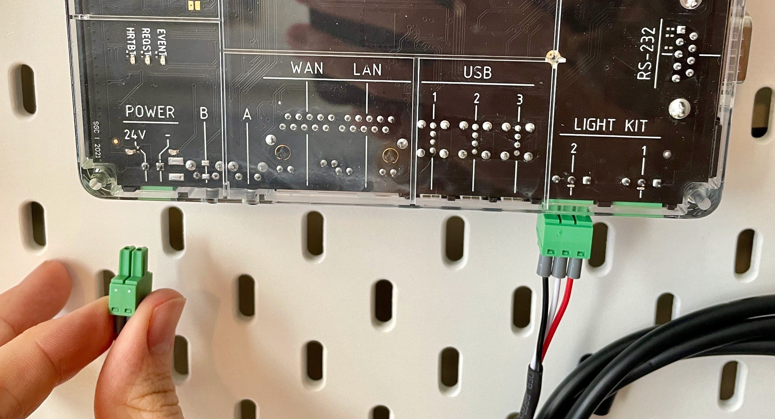
Attach the connectors to the corresponding inputs in the Edge IO,
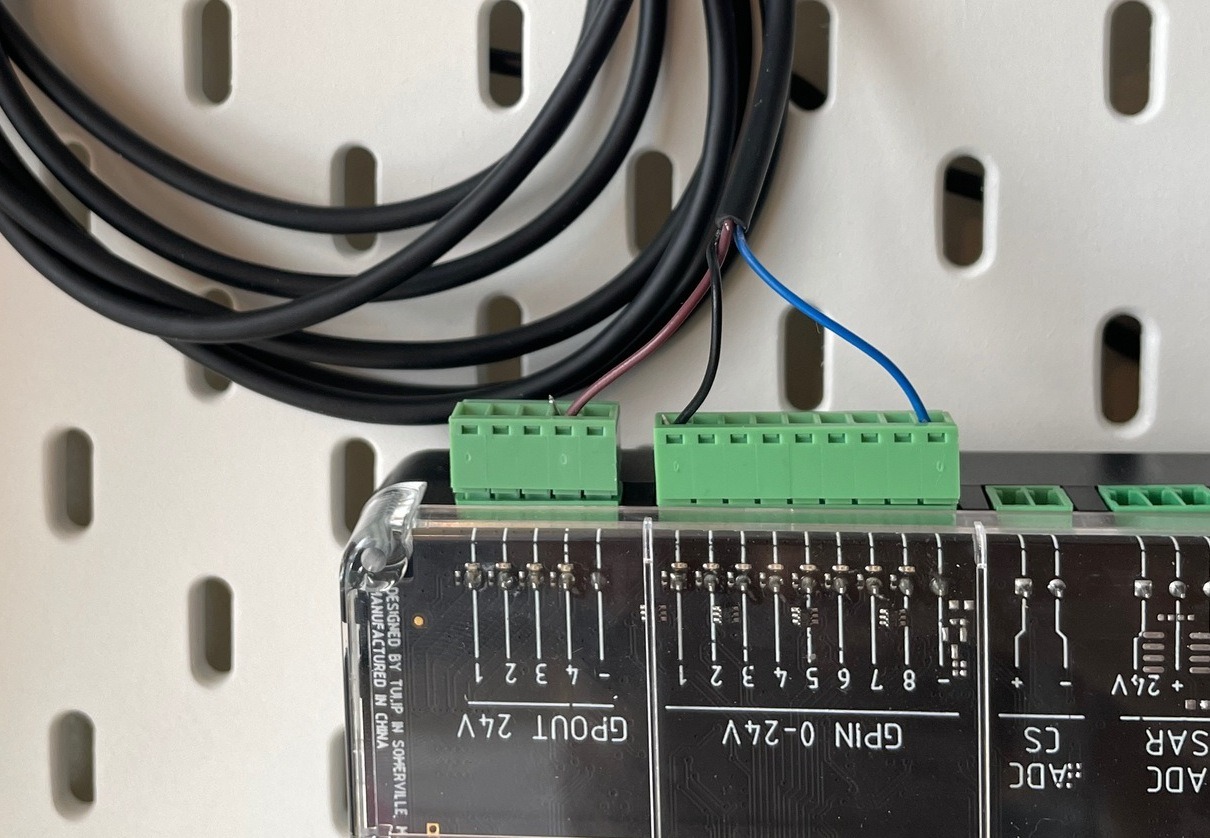
You can now plug the 2 pin connector to the Edge IO power and watch the power lights come on.
Testing the Break Beam Sensor
- Selecting Break Beam Sensor Unit Teston the Factory Kit Navigator Page
- Follow the instructions on the Barcode Scanner Unit Test Application and input an output pin and the corresponding I/O pin and hit test to power up the Break Beam.
- Move your hand back and forth in front of the sensor, and note whether the box changes color on the screen.
Having trouble? Contact us on live chat.
Turning on the power to the break beam sensor using Triggers
Log into Tulip and navigate to the step where you want to use the break beam sensor.
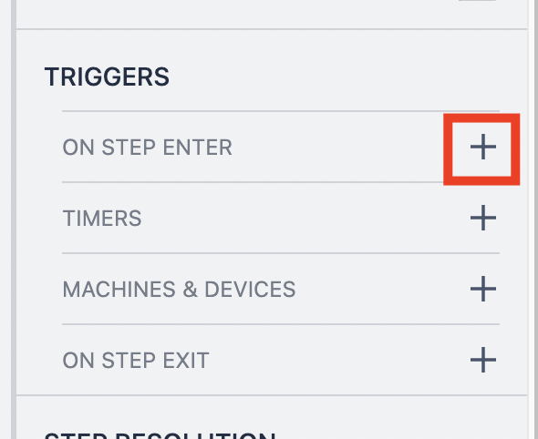
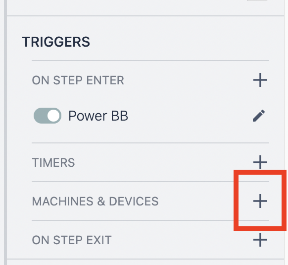
- Add an "on step enter" Trigger.
- Set your trigger to do the following-
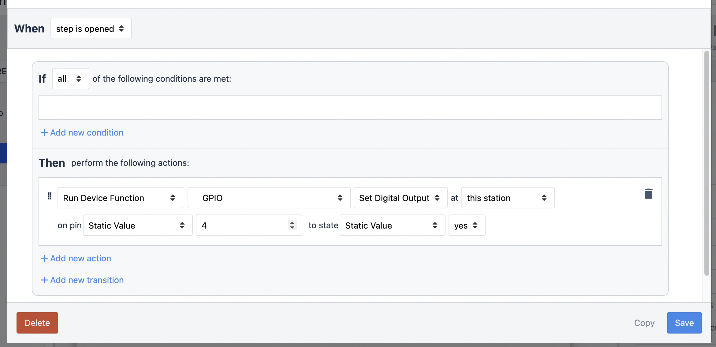
The trigger fires when the step is opened. That sends power to pin 4 (thus to the break beam).
For any app (or step) using a break beam that is powered in this way, this trigger MUST exist. It can be in the step or in the Base Layout.
Any pin can be the power output and it is defined in the trigger logic.
How to use the break beam sensor to drive app logic
Now that your break beam sensor is wired, you can use it to drive your application.
First, add a "Machine and Device" trigger.
The basic structure of a trigger is:
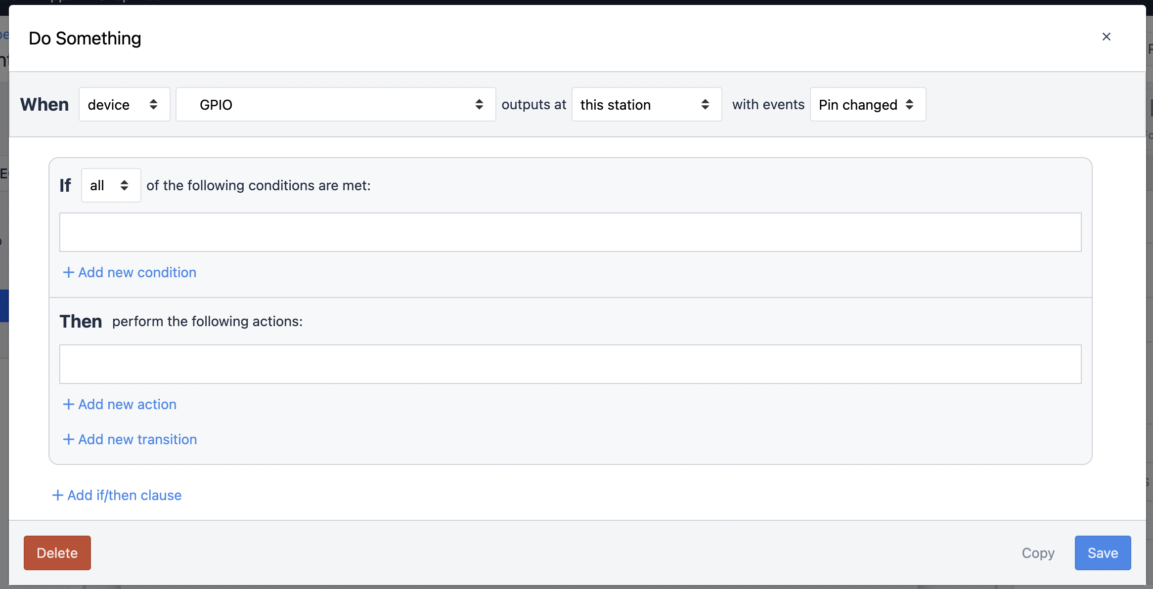
Note: if you have multiple pins changing on a step, you will need to add a condition specifying the pin the break beam is connected to.
Example Use Case:
An example of how to display a simple message to indicate the status of the break beam is below.
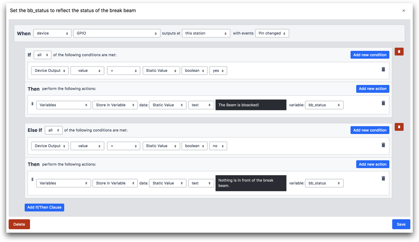
That’s all you need to do to be able to get started with your break beam sensor.
Next we are going to look at setting up the light stack included in your Factory Kit.