

Tulip offers flexibility in how you structure apps around machines. The right pattern depends on your team's technical maturity, process standardization, and budget.
Pattern 1: Composable machine apps (1:1 model)
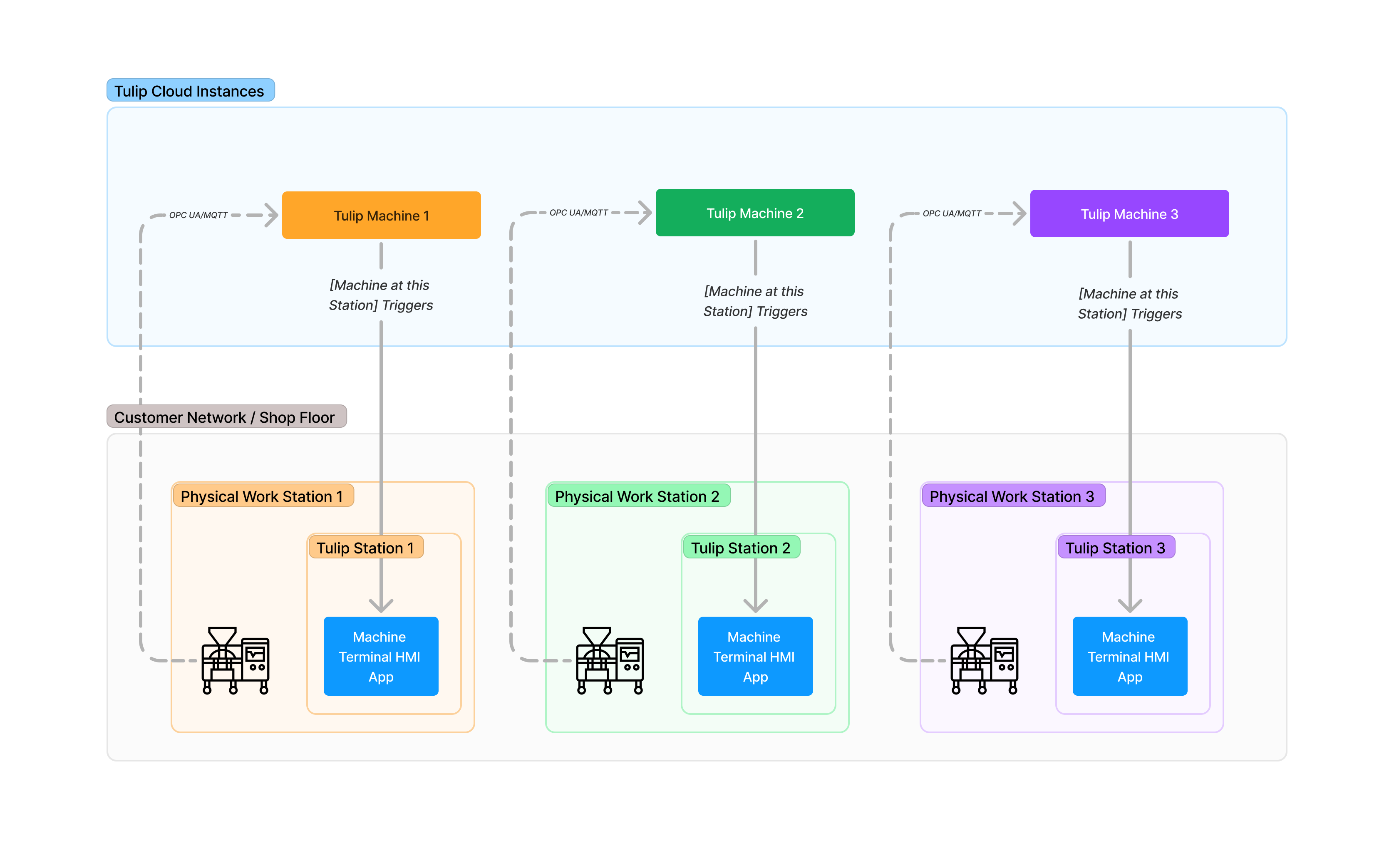
Structure: One machine → One app → One station → One terminal
Architecture diagram:
.png)
Use cases
- Entry-level citizen developers building their first machine monitoring apps
- Quick proof-of-concept deployments where simplicity outweighs efficiency
- Custom human processes per machine instance (e.g., Machine 1 requires unique inspection steps not applicable to Machine 2)
- Operations-led development where developers have multiple roles and limited time
Why this matters
This pattern physically maps software to hardware 1:1, eliminating abstraction. Developers can identify a machine on the shop floor and map it to its own app. This clarity reduces mental effort and makes troubleshooting intuitive.
Example
Scenario: A food and beverage manufacturer has 3 packaging lines. Each line has unique downtime reasons, part configurations, and operator workflows.
Implementation
- Create Machine Type: "Packaging Line"
- Create 3 machines: "Line A", "Line B", "Line C"
- Build 3 apps: "Line A Terminal", "Line B Terminal", "Line C Terminal"
- Assign each app to a dedicated station with a fixed terminal
Benefits
- Clear data isolation prevents cross-machine data corruption
- Easy to customize per-machine workflows
- Simple troubleshooting (problem is always in one self-contained app)
Limitations
- Requires one physical terminal per machine (hardware cost)
- Global app changes require updating 3 separate apps
- Not scalable beyond approximately 10 machines
Pattern 2: Machine assignment to station app
Structure: One machine type → One app → Multiple stations (machine dynamically assigned via station mapping)
Architecture diagram:
Use cases
- Standardized processes across identical machine types
- Full-time citizen developers comfortable with abstraction and trigger logic
- Horizontal scaling needed (10+ machines of same type)
- Centralized app maintenance is a priority
How it works
- Assign each machine to a station in Shop Floor > Machines (Configuration tab)
- In the app, use "at this station" trigger conditions to dynamically reference the assigned machine
- When the app runs on Station 1, it interacts with Machine 1. When it runs on Station 2, it interacts with Machine 2
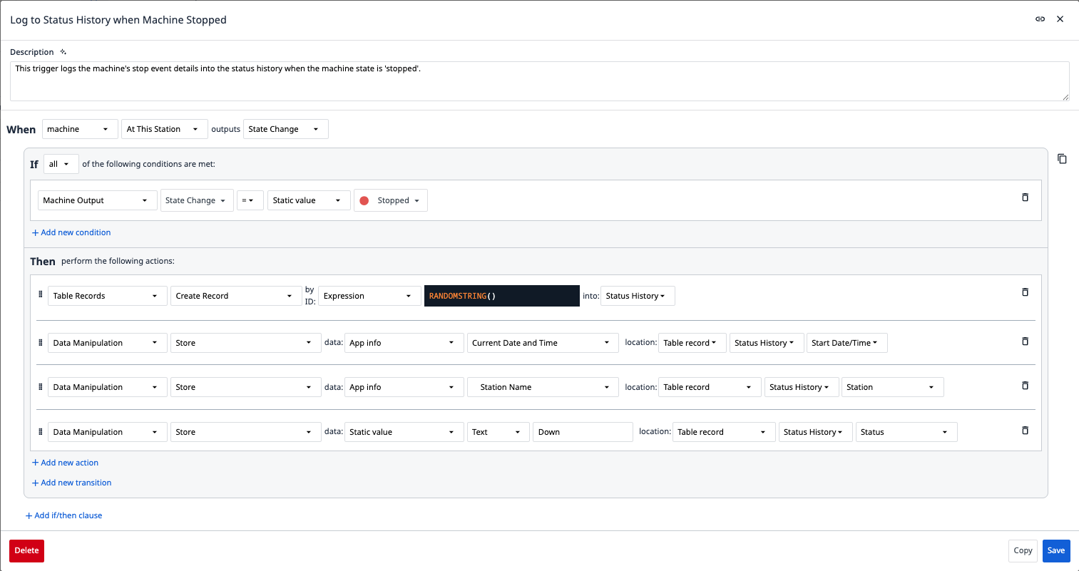
Example app trigger
When: Machine at this station outputs State Change
If: Machine Output / State Change = Down
Then: Create Table Record in 'Status History' Table.
Example
Scenario: Automotive tier-1 supplier has 15 identical CNC mills running the same production process.
Implementation
- Create machine type: "CNC Mill 5-Axis"
- Create 15 machines (CNC-001 through CNC-015)
- Build one app: "CNC Operator Terminal"
- Create 15 stations, assign one machine to each
- Deploy the single app to all 15 stations
Benefits
- Single app to maintain (global updates propagate instantly)
- Reduced app development time for fleet deployments
- Uses "at this station" trigger logic (built-in dynamic machine reference)
Limitations
- Still requires one terminal per station (hardware cost remains)
- All machines must be the same type with identical attributes
- Custom per-machine logic requires conditional branching (added complexity)
Pattern 3: Machine variable app (floating terminal)
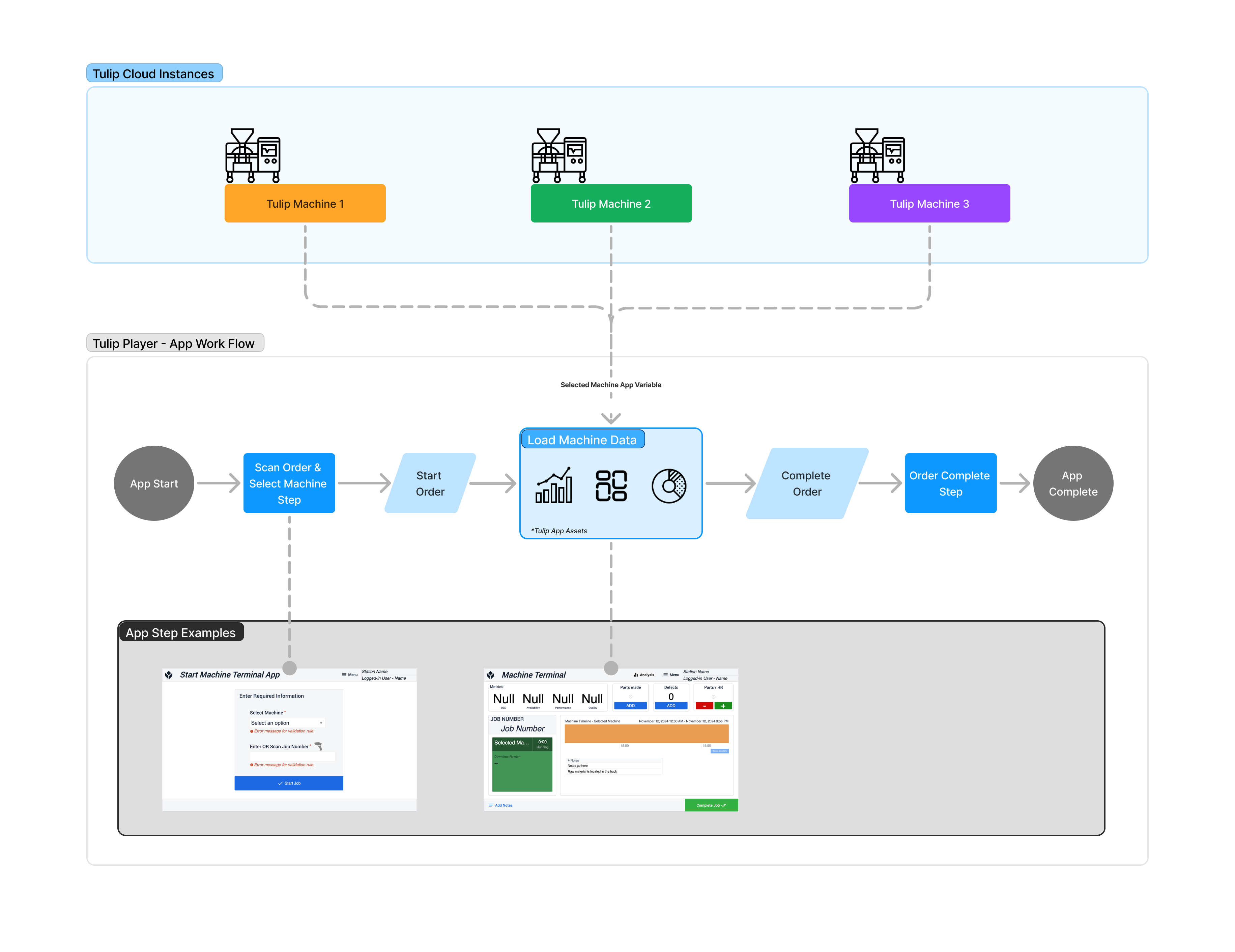
Structure: One app → Multiple machine types → Variable-based machine selection → Shared/floating terminal
Architecture diagram:
Use cases
- Budget constraints: Limited terminals available
- Floating operator model: One operator moves between machines with a shared iPad
- Machines don't require continuous monitoring: App only needs to run during active operations
Critical limitation: Not headless
This pattern does not support background/headless monitoring. If the app is closed, then no machine triggers fire. This pattern is only suitable for:
- Human-initiated data entry (operator logs defects, part counts)
- Ad-hoc machine inspections
- Scenarios where machines don't generate data when app is not running
How it works
- Create a machine variable in the app (e.g.,
selectedMachine) - Add a dropdown widget or QR code scan to populate
selectedMachineat runtime - Use
selectedMachinein all trigger references
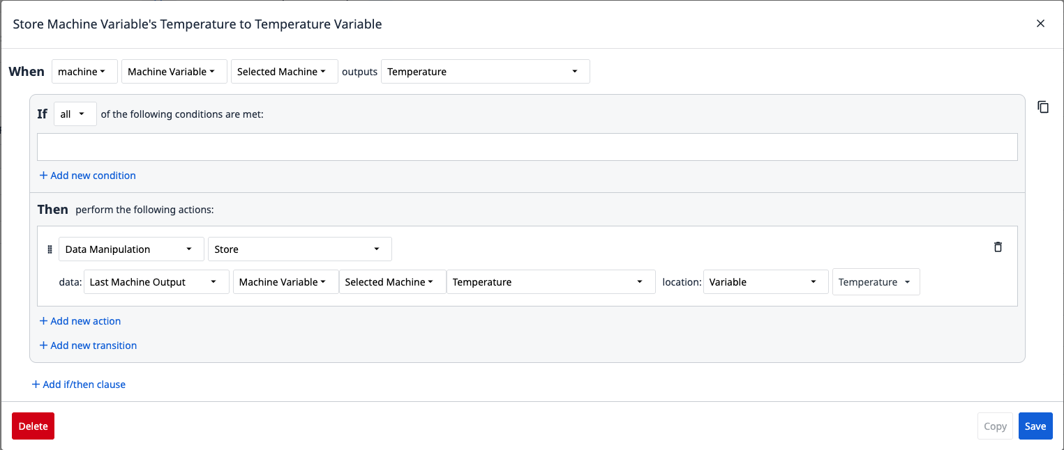
Example app trigger
When: machine Machine Variable 'Selected Machine' outputs {Attribute}
Then: Store Last Machine Output to Variable
Example
Scenario: Pharmaceutical lab has 5 analytical instruments that only run during scheduled tests. Technicians use a shared iPad to log test parameters and results.
Implementation
- Create 5 machines (HPLC-1, GC-MS-2, etc.)
- Build one app: "Lab Equipment Log"
- Add dropdown: "Select Instrument" → populates
selectedMachinevariable - Technician carries iPad between instruments, selects active machine, logs data
Benefits
- Minimal hardware cost (one shared terminal)
- Flexible machine selection at runtime
- Ideal for ad-hoc/intermittent workflows
Limitations
- Not headless - app must be actively running for any logic to execute
- No background monitoring when app is closed
- Complex state management (Which machine is currently active?)
- Not suitable for 24/7 OEE tracking
Architecture pattern decision tree
Use this decision tree to select the best pattern for your needs:
Further reading
Did you find what you were looking for?
You can also head to community.tulip.co to post your question or see if others have solved a similar topic!