Using the Banner PTL Driver
A guide to the Banner Pick-to-Light (PTL) Driver for Tulip
This article describes the capabilities and configuration associated with the Banner PTL driver in Tulip.
This driver will only be available for Player 2.8.0 and above. Please reach out to developer@tulip.co to put this on your instance.
Overview
In this article, we'll focus on the connection between Tulip and a Banner PTL device. We'll cover how to configure the connection and then explore the driver's capabilities, such as changing light colors, displaying text messages in various modes, and controlling light animations. You'll need the PTL device connected to your Windows PC and the appropriate Feature Flag enabled in your Tulip instance.
Configuration
To configure your Banner PTL device to be used with Tulip, follow the steps below.
Prerequisites
- Connect the Device: Plug your Banner PTL device into your Windows PC, typically via USB or a serial connection that provides a COM port.
- Windows Configuration: Ensure your Windows PC can recognize the connected PTL device and assign it a COM port.
Tulip Player Configuration
Connection and setup of the Banner PTL device are managed through the Tulip Player, typically within a dedicated driver testing application.
-
Navigate to Banner PTL Driver:
- Open the Tulip Player.
- Go to the "Driver Unit tests app" or a similar application containing the "Player Driver page".
- Click the "BannerPTL" button or navigate to its section.
-
Identify COM Port:
- Click the List serial devices button. This will query the system and display available COM ports.
- Identify the COM port corresponding to your connected Banner PTL device.
-
Register and Setup Device:
- In the unit test app (or your application's interface for this driver):
- Enter the identified COM port under the path field.
- Set the baud rate to
19200. - Set the device ID to
1(or as appropriate for your PTL device setup).
- Click the Register RTU button. This initiates communication with the specified device.
- After successful registration, click the Setup button to complete the device initialization.
(Placeholder for an image showing the Banner PTL connection interface in Tulip Player, with fields for path (COM port), baud rate, device ID, Register RTU, and Setup buttons.)
- In the unit test app (or your application's interface for this driver):
Troubleshooting
- Unable to List COM Port:
- Ensure the Banner PTL device is properly connected to the PC and powered on.
- Check Windows Device Manager to see if the device (or its USB-to-Serial adapter) is recognized and if a COM port is assigned.
- Try reconnecting the device or restarting the Tulip Player.
- Registration or Setup Fails:
- Verify the correct COM port (
path), baud rate (19200), anddevice IDare entered. - Ensure no other application is currently using the same COM port.
- Confirm the
CUSTOM_EDGE_DRIVER_BANNER_PTLFeature Flag is active. - Check the Banner PTL device documentation for specific setup or mode requirements.
- Verify the correct COM port (
Capabilities
The Banner PTL driver allows Tulip Apps to integrate with Banner Pick-to-Light devices connected to the Windows Tulip Player. This enables functionalities like controlling light colors, displaying messages, and managing animations for visual operator guidance.
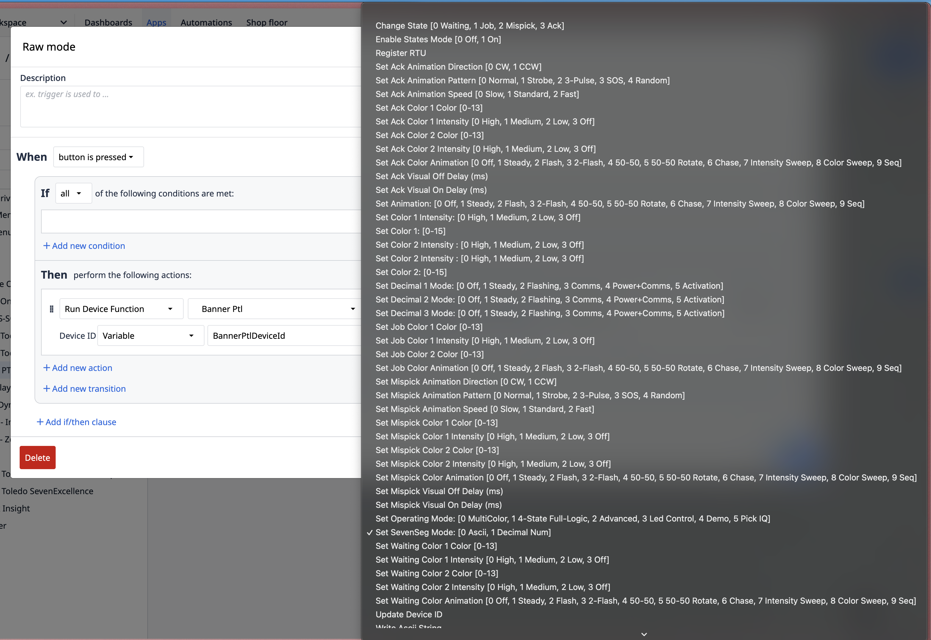
Functions
The following functions can be used in Tulip Triggers to interact with the connected Banner PTL device:
(Placeholder for a generic image illustrating Tulip trigger actions for a device driver.)
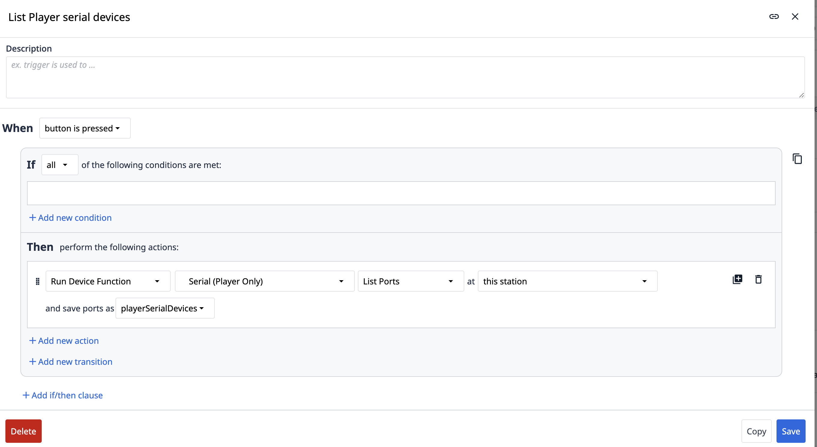
- List serial devices:
- Description: Queries the Windows Player machine and lists available serial (COM) ports.
- Inputs: None.
- Outputs: A list of available COM ports.
- Register RTU:
- Description: Registers the PTL device with the driver using its communication parameters. This is a prerequisite for further interaction.
- Inputs:
path: The COM port the PTL device is connected to (e.g., "COM3").baudRate: The communication speed, typically19200for Banner PTL.deviceID: The specific ID of the PTL unit (e.g.,1).
- Outputs: Status of the registration attempt (triggers an
OperationStatusevent).
- Setup:
- Description: Performs initial setup or configuration of the registered PTL device. Should be called after successful
Register RTU. - Inputs: None (assumes device is registered).
- Outputs: Status of the setup attempt (triggers an
OperationStatusevent).
- Description: Performs initial setup or configuration of the registered PTL device. Should be called after successful
- Set Color 1:
- Description: Changes the primary color displayed by the PTL device.
- Inputs:
colorValue: The desired color (e.g., "Red", "Green", "Blue", or a specific code supported by the device).
- Outputs: Triggers an
OperationStatusevent. Visual confirmation on the PTL device.
- Set Color 2:
- Description: Changes a secondary color displayed by the PTL device (if supported).
- Inputs:
colorValue: The desired color.
- Outputs: Triggers an
OperationStatusevent. Visual confirmation on the PTL device.
- Set ASCII Mode:
- Description: Switches the PTL device's display to expect ASCII character strings.
- Inputs: None.
- Outputs: Triggers an
OperationStatusevent.
- Write Input String:
- Description: Sends a text string to be displayed on the PTL device. The device must typically be in ASCII mode. The PTL might show this as a rotating or static string (e.g., "Hello").
- Inputs:
inputString: The text to display (e.g., "Hello").
- Outputs: Triggers an
OperationStatusevent. Visual confirmation on the PTL device.
- Set Raw Mode:
- Description: Switches the PTL device's display to a raw or numerical representation mode. Displaying an ASCII string like "Hello" in this mode might show its numerical/byte representation on the device.
- Inputs: None.
- Outputs: Triggers an
OperationStatusevent.
- Set Animation Mode:
- Description: Changes the animation pattern of the lights on the PTL device.
- Inputs:
animationMode: An identifier for the desired animation (e.g., "Flash", "Pulse", "Scroll", or a specific code).
- Outputs: Triggers an
OperationStatusevent. Visual confirmation of the changed animation on the PTL device.
- Disconnect / Unregister:
- Description: (Assuming a function exists to release the device) Disconnects or unregisters the PTL device from the driver.
- Inputs:
deviceID(optional, if managing multiple devices). - Outputs: Status of disconnection (triggers an
OperationStatusevent).
Events
The following events can be used in Tulip Triggers to react to information or status changes from the Banner PTL driver:
- Error:
- Description: Indicates an issue with the driver, communication, or device.
- Payload: Contains a
messagedetailing the error.
- OperationStatus:
- Description: Indicates the result of an executed command (e.g., Register RTU, Set Color, Write Input String).
- Payload:
command: The name of the function that was executed (e.g., "RegisterRTU", "SetColor1").status: "success" or "failure".message: Additional information about the operation's outcome.