- Print
How to use GPIO on Edge IO
Guide to reading digital inputs and writing digital outputs on Edge IO
In this article, you will learn how to read digital inputs and write digital outputs on Edge IO. Topics covered include:
- Technical specifications of Edge IO GPIO ports
- Using GPIO in Tulip apps with the Generic I/O driver
- Using GPIO with Machines and Node-RED
Technical Specifications
Edge IO has the following GPIO pins:
- 4 digital outputs
- 24V relay output
- Up to 500mA per pin
- 8 digital inputs
- 5-36V logic-level compatibility
- Input high voltage: 4V
- Input low voltage: 1V
It is best practice to use a PNP-type sensor to connect to the GPIO pins. If a NPN-type sensor is used, a high resistor must be used. All pins have an LED that will light when the pin is toggled high ("on").
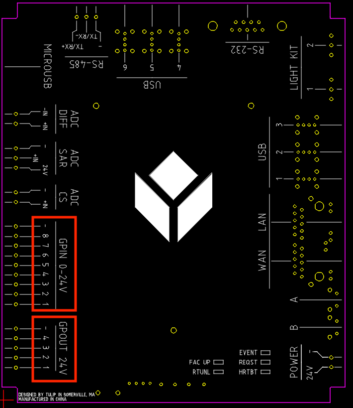
The pins are located as shown in the following diagram. Note that the input bank and output bank each have an additional (common) ground pin.

Using GPIO in Tulip apps
The Generic I/O driver on your Edge IO enables the following GPIO functionality in Tulip apps:
- Monitor pinUp, pinDown, or pinChange events on digital inputs
- Read digital inputs
- Write digital outputs
To learn about enabling the Generic I/O driver and how to use it in Tulip app triggers, please reference Using the Generic I/O Driver
Using GPIO in Node RED
Why might I use Node-RED to handle GPIO? Read further in this section if you want to:
- Use a digital input as the data source for a Tulip Machine
- read and/or write GPIO using logic at the edge, without needing the cloud
- Batch GPIO events before sending to Tulip to improve performance
- Implement a custom driver or custom logic to process signals before sending to Tulip
- Integrate a GPIO device that has existing 3rd-party Node-RED support
The Node-RED installation on Edge IO comes with the following custom Tulip nodes that allow you to interact with the GPIO subsystem. Full details on node usage can be found by a node and navigating to the "Help" tab in the sidebar.
Reading Digital Inputs
Add a tulip-digital-input node into your flow to either monitor pin changes (Run Mode: Continuous) or read a pin (Run Mode: On Trigger). For either option, you can select which of the 8 pins to read.

Writing Digital Output
Add a tulip-digital-output node into your flow to write values to the digital output pins. You can select any subset of the 4 pins to write.

Library Flows
The Edge IO comes with Tulip library flows pre-installed in Node-RED that allow you to interact with GPIO in Node-RED from Tulip. To learn about how to find and import Tulip library flows in Node RED, refer to Importing Tulip Node-RED Flows
gpio_to_machine_attr is a library flow that monitors a GPIO pin in Node-RED and writes the pin's value to a machine attribute. To use this flow, you will need to configure the tulip-digital-input node to choose the pin to monitor, and map the tulip-machine-attribute node to a machine attribute of one of your Machines. You can learn more about sending data from Node-RED to Tulip using the Tulip API here.

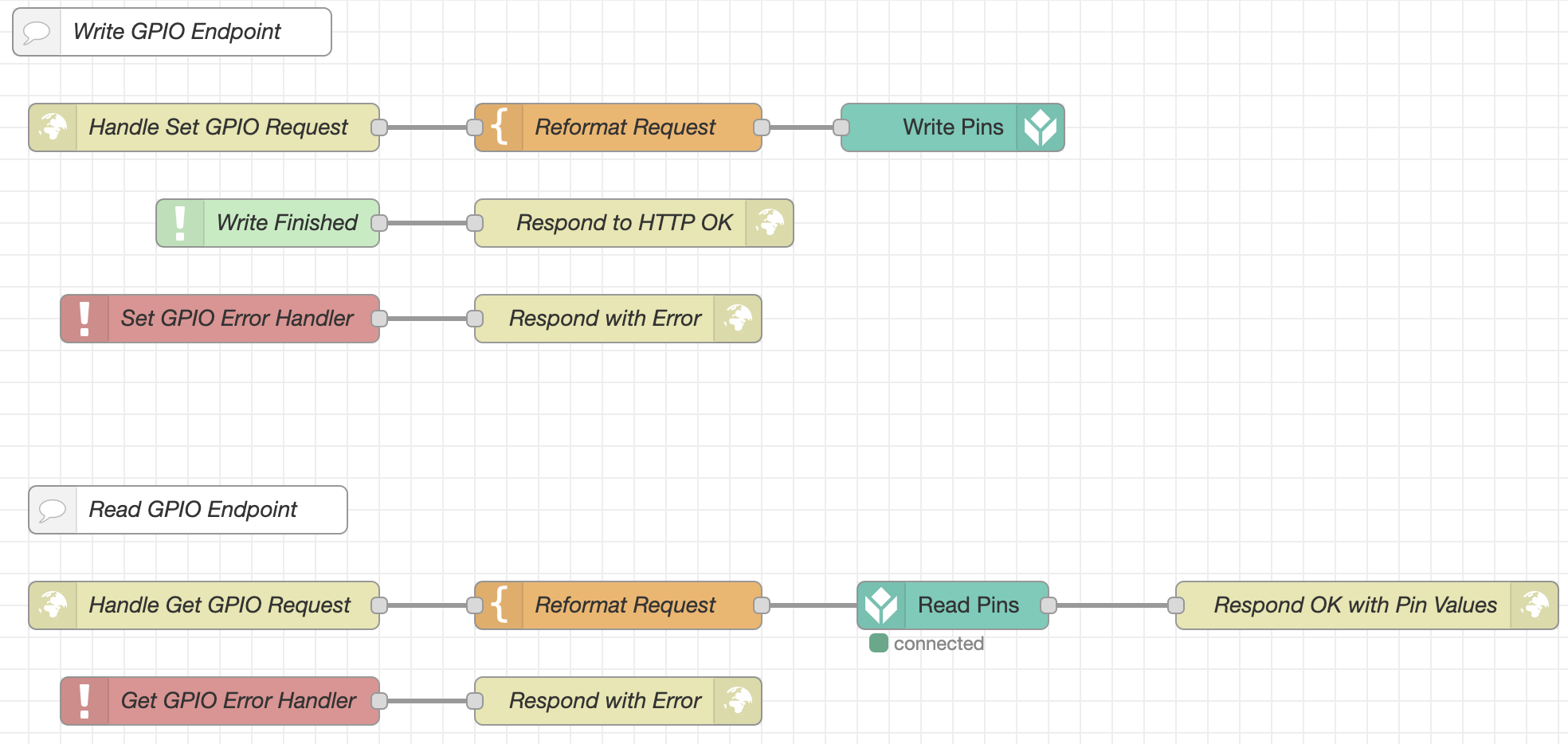
gpio_http_endpoints is a library flow that allows you to control GPIO pins from a Tulip app. You will need to create an HTTP connector that is configured to use the Edge Device's connector host, and create connector functions to hit the Node-RED HTTP endpoints configured in the flow. You can learn more about communicating with Node-RED over HTTP using the Edge Device's Connector Host here

Enabling Both Generic I/O and Node RED
It is possible to simultaneously enable both Generic I/O and Node-RED. This means that both Generic I/O and Node-RED can write values to digital output pins. If different values are written to a pin from multiple sources, the writes will be performed in the order that they are received. Before writing any pins, please confirm that they are not actively controlling any devices apart from the intended application. Tulip Edge Device GPIO should not be used in safety-critical applications.

