How to Setup Banner PICK-IQ Devices with Edge IO
- 15 Feb 2024
- 5 Minutes to read
- Contributors


- Print
How to Setup Banner PICK-IQ Devices with Edge IO
- Updated on 15 Feb 2024
- 5 Minutes to read
- Contributors
- Print
Article Summary
Share feedback
Thanks for sharing your feedback!
Learn how to connect Banner PICK-IQ devices to your Edge IO
This article covers the workflow to view data from a Banner Modbus device connected to your Edge IO locally in Node RED. It will utilize a Tulip Node-RED library flow that can be imported on your Edge IO and Tulip Tag nodes to send the data from Node-RED to Tulip.
You will complete the following steps:
- Hardware Setup: Wire the Edge IO
- Node-RED Setup: Import, edit, and deploy a Node-RED flow from the Tulip Library
What you will need is:
- An Edge IO registered to your Tulip account
- Banner Devices to connect to the Edge IO, such as:
- PTL110S-FF100TD3-QP150: Pick-to-Light
- K50PTCD4SQ: K50 Pro Touch Display with PICK-IQ
- K30PLSQ: K30 Pro Indicator with PICK-IQ Series
Update your Edge Device
Ensure your Edge Device is fully updated in order to prevent softlocking. If you run into issues connecting Modbus devices, restart Node-RED on your Edge Device.
Hardware Setup
| Wire Color | Edge IO Connection |
|---|---|
| Brown | GPIO+ |
| White | RS-485 TX/RX+ |
| Blue | GPOUT- |
| Black | RS-485 TX/RX- |
| Gray | Unused |
Node-RED Setup
Open the Device Portal on the Edge IO. Launch the Node-RED Editor using the following credentials:
- Username: admin
- Password: Your Edge IO password
See more information here to get started with Node-RED on Edge IO.
2a. Import Library Flow
To import the library flow, follow the steps in our Importing Tulip Node-RED Flows document. Importing the Tulip/Banner PICKIQ flow creates the PICKIQ tab in the editor.
2b. Overview of the Flow
This flow is comprised of four groups of nodes:
- Read Data
- Set Operating Mode
- Set Colors and Intensity
- Seven-Segment Display
Each is grouped by the particular functions for which they are used.
Read Data
The Read Data flow can be seen below.
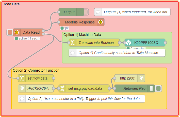
You have two options for sending the data from Node-RED into Tulip, using a Tulip Machine or using a Tulip Connector.
Option 1: Using a Tulip Machine
This method consists of the use of a Tulip Tag node for continuous data monitoring in Tulip through the use of a Tulip Machine. More information on setting up Tulip Tag nodes can be found in this article.
Option 2: Using a Tulip Connector
A Tulip connector can be used to actively poll for the current value of the data. This method works well for finding the current value, rather than continuously monitoring the data. An example connector for fetching data through an HTTP GET request can be found in the Tulip Library.
Set Operating Mode
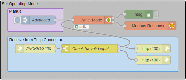
The Operating Mode determines which set of registers is used to control the device. The Advanced operating mode is used on the sample Node-RED flow. For other operating modes, refer to the Register Map.
Set Animation
Requires Operating Mode: Advanced.
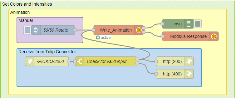
The above flow can be used to set the animation displayed on the device. You can either manually change the value by clicking the Inject node within Node-RED or change the value using a Tulip Connector function. The selected animation can determine how many colors are shown, as well as the motion of the colors.
Change Device Colors
Requires Operating Mode: Advanced.
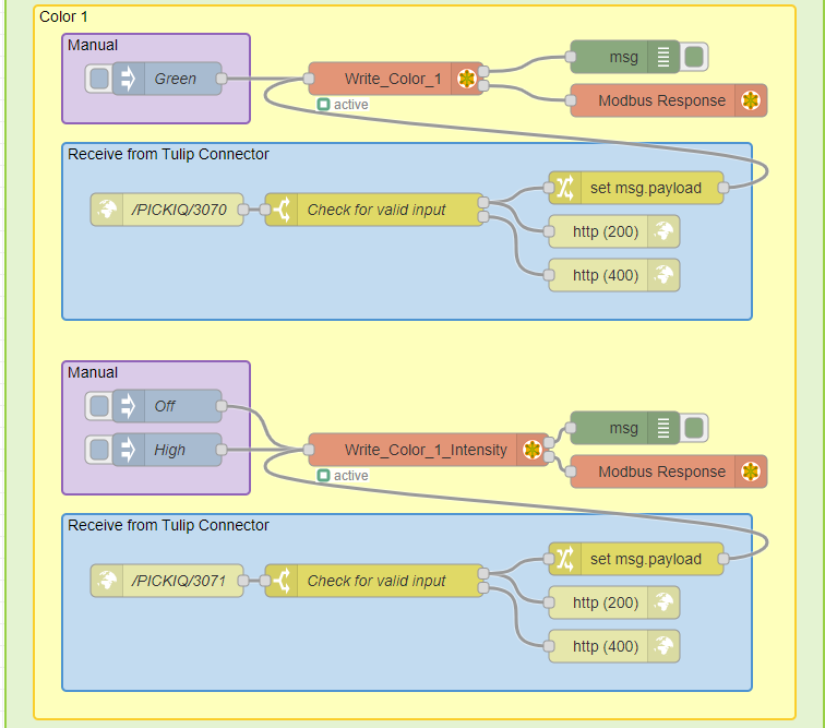
The above flow can be used to set both the color and color intensity displayed on the device. You can either manually change the value by clicking the Inject node within Node-RED or change the value using a Tulip Connector function. Depending on the selected animation, multiple colors may be displayed on the device. They may be denoted as Color 1 and Color 2.
Seven-Segment Display
The seven-segment display is only present on certain devices, such as the PTL110S and K50PTCD4SQ.
Set Input Mode
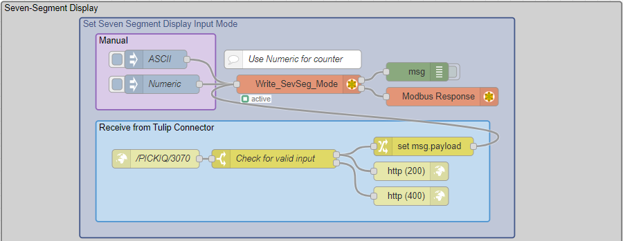
You must set an input mode before writing to the seven-segment display. The Numeric mode allows you to simply write numbers directly to the device. An example connector function can be found on the Tulip Library, under "PICK-IQ Unit Test". If you are interested in using the ASCII mode, please refer to the register map for details on the implementation.
Write to Display
Requires Seven-Segment Mode: Numeric.
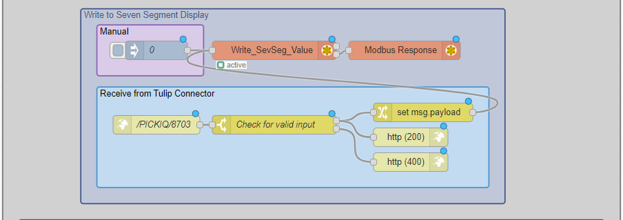
The above flow can be used to set the value displayed on the seven-segment display. You can either manually change the value by clicking the Inject node within Node-RED or change the value using a Tulip Connector function. This flow can be altered to create a counter, for example, incrementing every time the device is triggered.
Edit Decimals
The decimals on the seven-segment display can be controlled individually to present a variety of statuses.
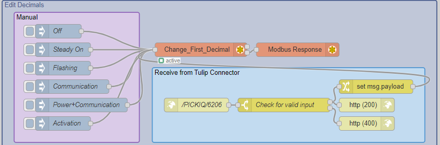
The above flow can be used to change the state of the decimals on the seven-segment display. You can either manually change the state by clicking the Inject nodes within Node-RED or by using a Tulip Connector function.
Change Unit-IDs
Each device has a Unit-ID (Default: 1), allowing you to address the specific device. If multiple devices are connected with the same Unit-ID, then all devices will be controlled by the Modbus nodes referencing the particular Unit-ID. If you want to individually control connected devices, you must:
- Connect your first device.
- Change the Unit-ID from Default: 1 to a new value (eg. 2).
- Double-click on any Modbus node that you want to reference the first device to edit the node.
- Change the Unit-ID field to your new value (eg. 2).
- Repeat for any other Modbus nodes that you want to reference the first device.
- Repeat for each new device.
A Modbus node can only address one Unit-ID at a time, therefore you may need to use multiple Modbus nodes to individually control multiple devices.
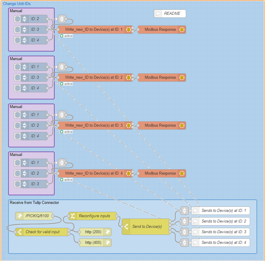
The above flow can be used to change the Unit-IDs of connected devices. You can either manually change the Unit-IDs by clicking the Inject nodes within Node-RED or change the Unit-IDs using a Tulip Connector function.
Was this article helpful?